Boden Albatross MkII

Get help and share Ideas
User avatar
zumpen
Donator '08, "09, "10, '"11
Posts: 35
Joined: Fri Aug 22, 2008 1:09 pm
15
Location: SWEDEN

Boden Albatross MkII

#1

Post by zumpen »

Hi.

Here is my first sketch, based on a Boden Albatross MkII. I raised the sheer to give a more soft profile.

Measurements: 5,2*2,2 meters
Hull weight: 450 kg (4 mm alu, bottom and sides)
Engine capacity: 100 HP
Speed: +30 knots


Image


/zumpen
Last edited by zumpen on Fri Sep 05, 2008 12:54 pm, edited 1 time in total.
User avatar
CTMD
Posts: 276
Joined: Sun Aug 31, 2008 5:26 pm
15
Location: Melbourne Australia
Contact:

#2

Post by CTMD »

The boat looks great. As a next step, draw in a cockpit sole about 150mm above the waterline at the transom sloped up by 1 degree and then check your bulwark/hull side heights. Your ali weight may be a little optimistic but could be achievable with 3mm plate, on a boat this size I'd use 4. We only use 3mm for decks and superstructures. 3mm hulls require a lot of extra stiffening and are hard to weld without "tin canning"
Chris Tucker Marine Design
Your Boat Your Way.
www.ctmd.com.au
warthog5
Posts: 198
Joined: Wed Jan 23, 2008 9:04 am
16
Location: Pensacola, Fl.

#3

Post by warthog5 »

The lines are wrong at the bow. that up and radical down is not smooth and flowing.

To high in the middle and to low at the bow.

Try again. Think Classic sheer line of the info mus Carolina Flair.

I personally hate droopy nosed boats. Cape Horn, Fountain and there are more.
"Just 'cause it's New, doesn't mean it's worth a Damn."
Bullshipper
Posts: 199
Joined: Tue Jan 08, 2008 11:53 pm
16
Location: Mexico

#4

Post by Bullshipper »

For a first draft, that's very nice.
User avatar
welder
Site Admin
Posts: 4668
Joined: Thu Jan 03, 2008 11:51 pm
16
Location: Whitesboro, Texas
Contact:

#5

Post by welder »

As said above ^^^^^^^^^ I would go with a thicker Hull material , 4mm or 5mm [ 5 on the hull and 4 on the sides ] the plate that thickness will cost a little more but you will save $ on the structural pieces and it wont oil can .

Then I would use 3mm for the Center console and other Bits and Pieces on and around the deck.

What type of Alloy Plate are you going to use , ie. 5086. 5083 ?

This is COOL , lets build a Boat !
Lester,
PacificV2325, Honda BF225
2386
User avatar
zumpen
Donator '08, "09, "10, '"11
Posts: 35
Joined: Fri Aug 22, 2008 1:09 pm
15
Location: SWEDEN

Thank you for your feedback!

#6

Post by zumpen »

Hi.

I sure appreciate your feedback in this project. Being a rookie here and building my first boat, I'll sure need all the assistance I can get. About the plate thickness, 3 mm was aimed to reduce weight. But I won't do that for the price of "oil-canning" and welding problems. So 4mm is now planned.

@CTMD: I'm glad you liked the sketch, I've spent countless hours on the web, evaluating every? down-under plate boat. You have some amazing designs to be inspired by. Could you please explain a little more about the "cockpit sole about 150mm above the waterline at the transom sloped up by 1 degree". My marine/ nautical English is a bit "rusty".

@warthog5: I tried to google for "Carolina Flair/ Flare", and visited Buddy Davis Boats. But I couldn't find any good pic's of this. Do you have an example pic or link to post?

@Bullshipper: Thanks!

@welder: For plates I will use 5083.

See ya!

/zumpen
warthog5
Posts: 198
Joined: Wed Jan 23, 2008 9:04 am
16
Location: Pensacola, Fl.

#7

Post by warthog5 »

Best I could do quickly.


Image
"Just 'cause it's New, doesn't mean it's worth a Damn."
User avatar
zumpen
Donator '08, "09, "10, '"11
Posts: 35
Joined: Fri Aug 22, 2008 1:09 pm
15
Location: SWEDEN

#8

Post by zumpen »

warthog5 wrote:Best I could do quickly.
Thanks! Now I see what you mean.

I modified the sketch a little, no "extended nose", and a little lower sheer. I kinda like this one better.

Why the raised sheer? Well, I usually go fishing in Lake Vättern, it's 150 km long, and 20-30 km wide. When the wind gets blowing along the lake, waves get very crazy. With wave amplitude of 6-8 feet, and wavelenght of 10-15 feet, it's like hell to ride in this.

Image

/zumpen
warthog5
Posts: 198
Joined: Wed Jan 23, 2008 9:04 am
16
Location: Pensacola, Fl.

#9

Post by warthog5 »

Bring the Stem up higher. About the height where the center upright of the bow rail is and then replot the line of the raised sheer.

What you have there is a Droopy nose. :(

Even the pix I posted could use a slight rise of the stem.

I'd rather see the bow area with the Stem slightly higher than the rest of the Sheer, if not then level with it, but NOT Droppy.
"Just 'cause it's New, doesn't mean it's worth a Damn."
User avatar
CTMD
Posts: 276
Joined: Sun Aug 31, 2008 5:26 pm
15
Location: Melbourne Australia
Contact:

Re: Thank you for your feedback!

#10

Post by CTMD »

zumpen wrote:Hi.
@CTMD: I'm glad you liked the sketch, I've spent countless hours on the web, evaluating every? down-under plate boat. You have some amazing designs to be inspired by. Could you please explain a little more about the "cockpit sole about 150mm above the waterline at the transom sloped up by 1 degree". My marine/ nautical English is a bit "rusty".
/zumpen
The sole is the floor you stand on. Making it 150mm (6in) above the waterline and then sloping it backwards so it can drain through scuppers in the after bulkhead will make it self draining and the boat a lot easier to run. Try doing your sketches either on graph paper or with a layer of graph paper underneith (so it can be seen through the paper you're drawing on).

Then do the following.

1. Draw a vertical line to represent the aft bulkhead and a horizontal line to represent the waterline.
2. Put a mark on the bulkhead 150mm up from the waterline.
3. Draw in you sole (floor) sloping up from this mark.
4. Find the top edge of the transom. For 100hp this will be approx 550mm aft of the back bulkhead. Height is dependant on engine selection and draft. Draw it at about 405mm above the waterline for now.
5. Draw in two lines parallel to your sole the first should be 750mm above it and the second 2050 above it. These are your preliminary sidedeck and cabin top heights (both can be varied however 750mm is pretty much the standard minimum rail height around the world.
6. Draw another vertical line 5.2m (or whatever you decide on) forward of the transom drawn in step 4.
7. Draw your boat around these lines.

Keep us posted on what you produce.
Chris Tucker Marine Design
Your Boat Your Way.
www.ctmd.com.au
User avatar
zumpen
Donator '08, "09, "10, '"11
Posts: 35
Joined: Fri Aug 22, 2008 1:09 pm
15
Location: SWEDEN

Draft #3

#11

Post by zumpen »

Hi.

Here is the latest draft. I integrated sheer-line and bow-height proposed from warthog5. And from CTMD I got measurements for self-draining floor and sidedeck height. This gives the boat IMO, a more robust look.
Thank you all for the comments so far.

Now I need to sit down and evaluate the designs a bit more.


Image

/zumpen
warthog5
Posts: 198
Joined: Wed Jan 23, 2008 9:04 am
16
Location: Pensacola, Fl.

#12

Post by warthog5 »

:D Don't you agree that it has better lines now?
"Just 'cause it's New, doesn't mean it's worth a Damn."
User avatar
CTMD
Posts: 276
Joined: Sun Aug 31, 2008 5:26 pm
15
Location: Melbourne Australia
Contact:

#13

Post by CTMD »

Bring the raised bow aft a little. It will make the boat look less bow heavy and also disguise the centre console a little.
Chris Tucker Marine Design
Your Boat Your Way.
www.ctmd.com.au
User avatar
zumpen
Donator '08, "09, "10, '"11
Posts: 35
Joined: Fri Aug 22, 2008 1:09 pm
15
Location: SWEDEN

#14

Post by zumpen »

warthog5 wrote::D Don't you agree that it has better lines now?
Yeah, this looks better. I'm glad you insisted about getting rid of that "droopy" look.

This is very fun, me sketching boats in a little cottage, in the deep forest of Sweden, getting feedback from US and Australia!

I'll try to extend the sheer a little longer aft, as CTMD proposed, but this week it's just hard work at the plant.

See ya.

/zumpen
Ironwoodtuna
Donator '09 '10
Posts: 510
Joined: Wed Jan 09, 2008 9:27 pm
16
Location: Montauk, NY

THINK TWICE - CUT ONCE - AND WELD ONCE!!!

#15

Post by Ironwoodtuna »

Zumpen,

I think that your attemps in drawing the hull are not practical to bend with aluminum as shown. I am not putting you down in any way but if you look at the beautiful line that Warthog drew you would admit that I really think that Warthog pinned it on the money. I am sure he wouldnt be offended if you took his nice lines.

Your going to spend a lot of time, money and hard labor of love building your girl, and no member wants you to waste any of the above in a lesser project that has possible design/build faults.

We can't wait to see the first pictures as you lay it out in your jig. Good luck and I would take some balsa wood and start playing with trying to build a scale model of your hull. If you can do it on balsowood you can do it in aluinum. If you can't then alloy won't work either.

Try it and you'll agree. Plus you can work out alot of other design issues. I built a scale model with my boat. Things changed quickly when I did, then John Taylor from Ironwood showed me how muck more you can do if you understand what can be done with aluminum.

Good luck, we are waiting for the first picture post. Marty
ImageImage
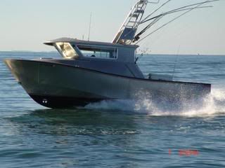
"IRONWOODTUNA" the Alloy Sportfisherman Battleship!
User avatar
Sculpin
Posts: 905
Joined: Tue Apr 22, 2008 10:10 pm
15
Location: Vancouver Island(The Rock), British Columbia

#16

Post by Sculpin »

I'm not a big fan of the dropped bow look either but with that said I don't see why you shouldn't build what "YOU" want. After all it is ultimately your vessel and should be built how you want it and how you want it to look. Good luck and I envy you for having the time to build your own.
John
Sculpin
23' Edwing

"Trying to go for tuna on the cheap you are asking for trouble. The ocean is a mean LITTLE GIRL that wants to kill you". - Shawn Hillier
warthog5
Posts: 198
Joined: Wed Jan 23, 2008 9:04 am
16
Location: Pensacola, Fl.

#17

Post by warthog5 »

The pix I posted is actually a Plywood stitch & Glue hull.

My buddy is building one and I have straightened him out when he get's stumped.

Here it is laying upside down and after I painted the bottom.

There is a little tourchering of the plywood in this.


Image

Image

Image

Image

Image

Flipping party

Image

The bow area needs a little work to straighten it out. This seems to be something in the plans as it happens on all of them, but the designer will not hear that it's his fault.

Image
"Just 'cause it's New, doesn't mean it's worth a Damn."
User avatar
Sculpin
Posts: 905
Joined: Tue Apr 22, 2008 10:10 pm
15
Location: Vancouver Island(The Rock), British Columbia

#18

Post by Sculpin »

Yuk!!!! Let's stick to alloy please :D . That is an amazing looking hull for stitch and glue. I often thought of building a Tolman skiff just for the heck of it and to do something out of wood for a change.
John
Sculpin
23' Edwing

"Trying to go for tuna on the cheap you are asking for trouble. The ocean is a mean LITTLE GIRL that wants to kill you". - Shawn Hillier
User avatar
zumpen
Donator '08, "09, "10, '"11
Posts: 35
Joined: Fri Aug 22, 2008 1:09 pm
15
Location: SWEDEN

Re: THINK TWICE - CUT ONCE - AND WELD ONCE!!!

#19

Post by zumpen »

Ironwoodtuna wrote:Zumpen,

I think that your attemps in drawing the hull are not practical to bend with aluminum as shown. I am not putting you down in any way but if you look at the beautiful line that Warthog drew you would admit that I really think that Warthog pinned it on the money. I am sure he wouldnt be offended if you took his nice lines.

Your going to spend a lot of time, money and hard labor of love building your girl, and no member wants you to waste any of the above in a lesser project that has possible design/build faults.

We can't wait to see the first pictures as you lay it out in your jig. Good luck and I would take some balsa wood and start playing with trying to build a scale model of your hull. If you can do it on balsowood you can do it in aluinum. If you can't then alloy won't work either.

Try it and you'll agree. Plus you can work out alot of other design issues. I built a scale model with my boat. Things changed quickly when I did, then John Taylor from Ironwood showed me how muck more you can do if you understand what can be done with aluminum.

Good luck, we are waiting for the first picture post. Marty
Hi.

Thanks for your input! Building a model with balsa sounds like a good idea, I originaly thought about using a cardboard model, scale 1:20, but I think balsa sheets will be more "true", in bending and twisting properties.

Lots of work to be done, fortunately the Swedish winter is dark, cold and looooong.

/zumpen
User avatar
JETTYWOLF
Contributor/donator/Location Nazi
Posts: 6074
Joined: Sun Jan 06, 2008 9:11 pm
16
Location: Tree-hugger, USA...they call it FLA.

#20

Post by JETTYWOLF »

Just for the record, "I'm not asking what the hell stitch and glue is"
sounds like something I don't want to be involved with, myself.

But pretend someone is asking....just for boat knowledge sake.

I think we can mention wood here. But of course there's no F-talk.
So it could be safe.

:wink: :wink:
User avatar
welder
Site Admin
Posts: 4668
Joined: Thu Jan 03, 2008 11:51 pm
16
Location: Whitesboro, Texas
Contact:

#21

Post by welder »

Wood is cool , thats where it all started but don't push it.

:D
Lester,
PacificV2325, Honda BF225
2386
User avatar
CTMD
Posts: 276
Joined: Sun Aug 31, 2008 5:26 pm
15
Location: Melbourne Australia
Contact:

#22

Post by CTMD »

JETTYWOLF wrote:Just for the record, "I'm not asking what the hell stitch and glue is"
sounds like something I don't want to be involved with, myself.

But pretend someone is asking....just for boat knowledge sake.

I think we can mention wood here. But of course there's no F-talk.
So it could be safe.

:wink: :wink:
:twisted: No wood talk here.....

To stitch and glue an "aluminium" boat you develop the panels as per a plate boat and then drill a series of holes along the edges. Panels are then wired together and then glue coves are added to the inside corners. Wires can then be removed and outside edges can be glued/taped. These days its more like staple and glue. Basically its a way to build boats out of flat panels and the designs are very similar in nature to Plate boats.

:twisted: 8)
Chris Tucker Marine Design
Your Boat Your Way.
www.ctmd.com.au
User avatar
zumpen
Donator '08, "09, "10, '"11
Posts: 35
Joined: Fri Aug 22, 2008 1:09 pm
15
Location: SWEDEN

TIG welding course?

#23

Post by zumpen »

Hi.

Today I got in contact with a teacher in welding. He offered a one week TIG welding course for about USD 2000. I think this would be a good investment for the future. I've only done MAG on steel before, so I sure could do with some professional training with the TIG.

/zumpen
User avatar
JETTYWOLF
Contributor/donator/Location Nazi
Posts: 6074
Joined: Sun Jan 06, 2008 9:11 pm
16
Location: Tree-hugger, USA...they call it FLA.

#24

Post by JETTYWOLF »

No wonder why I've never heard of such a thing.

I'll stick to my welded...plate.

Yeah, lets get back to Zumpen's boat welding.
User avatar
zumpen
Donator '08, "09, "10, '"11
Posts: 35
Joined: Fri Aug 22, 2008 1:09 pm
15
Location: SWEDEN

Re: Boden Albatross MkII

#25

Post by zumpen »

Hi.

Long time no see, so here's a little update:
My 10 days of education and certification in TIG Aluminium welding is scheduled to start Dec. 4. That is my own christmas gift . :lol:

/zumpen
Post Reply Previous topicNext topic