Welding Tricky Corners

Mods and custom builds
ARMOR
Posts: 12
Joined: Tue Aug 19, 2014 2:07 pm
9

Welding Tricky Corners

#1

Post by ARMOR »

Folks,

Any good advice on welding tricky corners? It gets pretty tough when you cannot maintain gun angle, gas coverage, and keep uphill. Most times this is not a problem as you are not normally welding into the corner this tight. However, in this case this is a water tight bulkhead. A flexible gooseneck would be nice, but I don't think it would be all that much better. Any thoughts on stopping short and just filling the corners with 5200? It certainly isn't structural.

Image
Last edited by ARMOR on Sun Oct 19, 2014 10:51 pm, edited 2 times in total.
kmorin
Donator 08, 09, 10, 11, 12, 13, 14, 15, 16, 17, 18, 19, 20, 21, 22, 23, 24
Posts: 1743
Joined: Mon Aug 18, 2008 1:37 am
15
Location: Kenai, Alaska

Re: Welding Tricky Corners

#2

Post by kmorin »

Armor, the link didn't display on my system so I can't see the image to reply. But.. if we can get the image posted of the weld area and its narrow access, and learn what type of gun you're using (?) I think we can make some suggestions that might help?

There is nothing wrong with aluminum MIG downhill welds, they do take a little prep and practice but not all vertical welds need to be uphill, just a note there.

Cheers,
Kevin Morin
Kenai, AK
kmorin
ARMOR
Posts: 12
Joined: Tue Aug 19, 2014 2:07 pm
9

Re: Welding Tricky Corners

#3

Post by ARMOR »

Kevin,

Sorry, while you were posting the response I was figuring out how to get the photos posted. Was using a Python push/pull with a Miller gooseneck on a 350P, but just upgraded an Alumafeed 350MPa, still using the same gun.
kmorin
Donator 08, 09, 10, 11, 12, 13, 14, 15, 16, 17, 18, 19, 20, 21, 22, 23, 24
Posts: 1743
Joined: Mon Aug 18, 2008 1:37 am
15
Location: Kenai, Alaska

Re: Welding Tricky Corners

#4

Post by kmorin »

Armor, several remarks, first is; that frame corner would be mouse holed in many designer's work. The 90 deg corner fit of the frame would be missing a corner so the three (horizontal left to right, horizontal right to intersection and three the vertical welds would not meet to form an stress raiser of overlapping welds.

As a reference I suggest you may want to see Dave Gerr's opinion on weld joint preparation in his book Boat Strength where some typical joints are shown for concept illustration. http://www.amazon.com/exec/obidos/ASIN/ ... 20-3189700 just a thought in regard this type of design element.

All the welds I can see a 'cold' or have 'toe and top' fusion deficiencies, but then dark photos of all grey aluminum weldments are notoriously hard to 'see' if the photos aren't artificially brightened and some edges sharpened in post processes. The image on my screen is a little out of focus too, so that may contribute to my understanding of the welds?

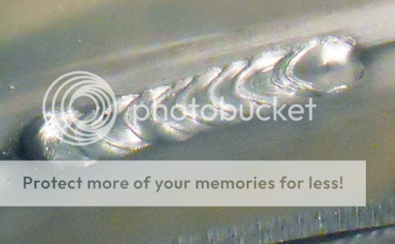
My test for toe and top fusion lines is to get very close to the bead, and make sure the tiniest ripple lines, NOT the puddle's edges overlapping in the line of the weld, at the very edges of the welds at the top and bottom of the weld or the 12:00 and 6:00 O'clock edges (9:00 is toward the welder and 3:00 is the 'back' where the puddles overlap if your whipping the welds as shown here.) Along these two main edges, I consider any MIG aluminum weld cold if the lines are not flowing into the parent metal smoothly AND I consider the weld too hot (long arc spray) when the edges are not rippled enough to show the wire droplet transfer and freeze in those flow lines.

Image

here is a cold weld, the edges of the puddle top and bottom are just very slightly rolled up, or have a pronounced edge to the parent metal, indicating the puddle may be #1 too full or #2 too cold to have full melted parent metal fusion. This cold weld was done to contrast the image of little bit more wattage and a little better fusion lines.

Image

IN this image the top and toe of the weld's puddle edges are flowing into the parent metal, indicating #1 that wire speed was a little lower allowing just a bit less puddle filling OR #2 the amperage/voltage/wattage was just little higher so the amount of heat melted the parent metal to the very edges of the puddle before the entire puddle froze/cooled/chilled to solid state.

So, it may be the photo being a tiny bit fuzzy, and the contrast and lighting just a bit dark and I therefore am not making a fair view of these welds. But.... If I do see them correctly I'd would have them at higher amperage/wattage and wire speed in order to get better fusion lines.

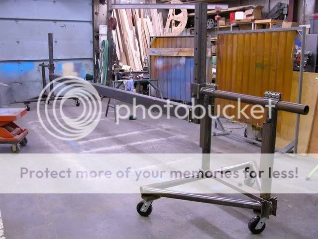
The regularity of the beads needs a little practice before welding on a boat, but if you're working below your knees while kneeling or crouching in the bilge, then you'll see why I refuse to do that work anymore. ( I can't deliver decent welds that I can live with) so... I use a rotisserie fixture named after Mr Jack Davis, a fabricator in Oregon whose idea it was for me. This allows the position welds to be controlled for access and not crouching to do less than optimal welds. I'm old and fat so I need every single advantage I can get.

Image

Davis Jig welding and building fixture shown in the small version

Image

Longer and taller Davis Jig with the bottom of a 25'LOA skiff mounted and being welded out inside. All the welds become horizontal or nearly flat almost all while standing flat footed on the shop floor or a step stool.

I'd have welded the vertical weld in the picture down hand, not uphill and I'd have beveled the cutout frame's edge where the weld was going to be put, and I'd have notched/nipped/mouse holed/limber holed the bottom 1" of that frame to stop the vertical weld above the two horizontal welds and the right to left horizontal would also have been stopped short of the left to right weld by the limber hole.

I hope you've gone to MK to get the ceramic pellet contact tip AND the gun drive rolls kits they both seem to make the gun run a lot better in my opinion.
Hope to have helped with another point of view? Not sure what works for one builder is all that helpful for another unless they're in the same shop long enough to iron out all the transfers of information? I rely on the break bend test, when in doubt I set up the weld on coupons then break them and see what I've got?

cheers,
Kevin Morin
Kenai, AK
kmorin
ARMOR
Posts: 12
Joined: Tue Aug 19, 2014 2:07 pm
9

Re: Welding Tricky Corners

#5

Post by ARMOR »

Kevin,

Appreciate the feedback. I agree on the use of rat or mouse holes, hence the consideration of just stopping short and laying down some 5200. In this case, as mentioned, it simply a bulkhead. The structural members all have rat holes.

So, the question is what are the thoughts on stopping short and applying sealant to corners?

It would certainly be a time saver when considering how tight some of them get.

As far as the welds go, they are ok. They do look much colder in the pictures than in actuality. The lighting is poor and the camera was from a phone, they look better in person. It is also welding 1/8” to a ¼” bottom. As mentioned, the access is tight; with the gun in the hole it is welding blind. Normally one would just have a couple 3” or so welds here which would have been much easier. Could they look better? Certainly. (straight gooseneck on order) A well thought out design and order of operations could have avoided some of these challenges. More experience never hurts either. As you essentially point out with the use of your rotisserie, bench top welds always look better unless you practice inside a box laying on your stomach.

No real issues with the MK gun. I rebuilt it a while back. Not sure of all the parts I used, but I do run insulated drive rollers as well as Bernard cups and tips (much cheaper), and it all seems to work.

From welding class I have burned in my brain to never weld downhill. The instructor challenged us with a BFH test of downhill welds versus uphill. (Steel) Every downhill weld broke, no uphill welds broke. I can weld AL downhill fine, the key is gun angle, but mostly avoid doing so. I can’t say I've ever bend tested a downhill aluminum weld as I have avoided it as much as possible.

I do have David Geer’s book(s), but for welding references, the best I have found are the AWS publications. I have both D3.7 Guide for Aluminum Hull Welding and D1.2 Structural Welding (aluminum).


:beer:
kmorin
Donator 08, 09, 10, 11, 12, 13, 14, 15, 16, 17, 18, 19, 20, 21, 22, 23, 24
Posts: 1743
Joined: Mon Aug 18, 2008 1:37 am
15
Location: Kenai, Alaska

Re: Welding Tricky Corners

#6

Post by kmorin »

Armor, I forgot and didn't pay attention to the fact you'd said it was a bulkhead so it needed to be sealed.

I'd weld the seal- not calk. I only use calk as bedding or insulation and there sparingly if possible. The weld I'd do is down (gun to the right), starting a few inched up the vertical, moving down and then pulling the gun to the left leading the weld to the left so I could see as I'm a right handed torch welder. I'd be working from he left side of the gun for visibility and reach. As you say very tight place to weld, so I use the rotisserie or plan to do welds like these earlier in the sequence of weldout.

I would never use sealant of any kind (that I've seen) in any bulkhead seal in a welded boat. I'd weld every seam, but as you've mentioned- since its mainly a sealant, why not weld down hand even if you think that is a substandard weld? Its one world of improvement over glue.

The down hand aluminum break bend is not the same as steel. Besides steel as a model for aluminum is not valid. And last; how many boats hulls has the weld teacher built? If its more than a couple dozen I'm willing to listen to his ideas, less than that and I'll just go with my own experience.

I've been told by lots of folks that one or another 'method' I use won't work but they all still floating. Dave Gerr has mentioned in print and other forums that aluminum can't be welded below 1/8" in thickness, but I have welded less than half that on a regular basis for decades, so; while I'm willing to respect others' opinions for their own experiences- I have experiences that don't always match so I'll rely on mine over others, and leave them to stay with their ideas over mine.

You can, anytime you want, set up some coupons and give down hand a try, single side, double side, beveled and butt T edges; they'd all give good information in my experience. That is why I always bevel bulkhead welds, both to the hull bottom and sides, and I also bevel lots of other places; but get told "you don't need too".

One other item about bulkhead seams done down hand. What weld failure test is appropriate? I mean we usually use the back bend where the T coupon is pulled over the face of the weld to see when it fails- right. But what does that imply for a boat's catastrophic failure event? It implies the bulkhead's weld has been pulled @ 90 deg over the bottom or topsides -along the length the keel! In other words an explosion of such power the entire bulkhead was 'back bent' over the weld.

I think a more realistic test is to cut a section of the T fillet coupons and crush then in a press. The T of the fillet up, the flat of the T on the press and then crush the two pieces and the weld connecting them. Even reversing the test crush orientation is good information. This simulates a T-bone boat collision of a huge cargo ship driving into the side of your boat ( :titanic: ) or.... in the case of the bottom it simulates the boat being dropped by a wave onto a piling or other sharp object where the forces can be concentrated. :eyepop:

Now, how did the weld fair? In my experience of repairing and surveying the damage to many of my boats that were landed on rock beaches in a dry breaking surf, carrying huge loads; the welds held the two pieces of the hull together and the entire area dented or bent inward but the welds were in tact.

I blew up a tank one time that taught me a lot of lessons. The tank's wall was 1/8" and the baffles were welded down hill inside the tank before the top was welded on.

Image

this scan of a Polaroid of the trophy is not all that clear but what this 'weld test' showed was the entire area around each of the baffle weld stitches done downhand on the 1/8" plate tore the plate away. The welds held the parent metal of the baffle and the sides together but the tear of the sides was at the HAZ around each weld. I implied then and do now that this meant the weld 'beat the metal' in a somewhat worst case test.

Not all weld tests or techniques are useful for hull work simulations or planning. Down hill welding MIG aluminum is a completely legitimate weld where you're weld thin sheet (<0.187"- 3/16") to the same or thicker materials. These welds can be done with 0.045" wire or 0.035" wire but the heavier wire allows faster travel and higher wattage giving better wetting at the higher speeds.

99% of Americas high pressure pipelines are welded downhand, root, hot and even filler passes all downhand with stick!

AWS barely cover the smaller boats with 1/8" structural elements and are written to protect insurance and finance companies- which is fine those folks do need protection from welders without adequate skills who may produce substandard work. They are very conservative as a result, and I don't find them addressing thin plate construction.

What I'm pointing out is that the average purely welded aluminum boat is overbuilt to a fact of from 2 to 20 in most cases. In the case of not doing a down hand weld because they don't in ship yards- its not an apples-to-apples comparison. At least I don't see the direct correlation.

When you try some thin material down hand test weld coupons and test them you'll see that continuous welding does have a high degree of structural integrity even if applied in the downhand orientation. If you can already do these welds - then all you need are some coupon tests to convince yourself you can rely on them?

Cheers,
Kevin Morin
Kenai, AK
kmorin
ARMOR
Posts: 12
Joined: Tue Aug 19, 2014 2:07 pm
9

Re: Welding Tricky Corners

#7

Post by ARMOR »

Kevin,

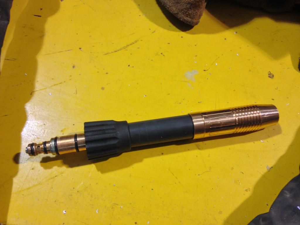
Thanks for the info and willingness to share your experience, it is quite helpful. I am still very much learning the art of boatbuilding. (it's an expensive education) The MK straight gooseneck showed up yesterday. I was hoping to try it out, but ended up being short on the correct MK tips.

Image

It seems like I may be able to get a much better gun position in the tight spots. With the angled gooseneck there is nowhere for the handle to go and keep a push going.

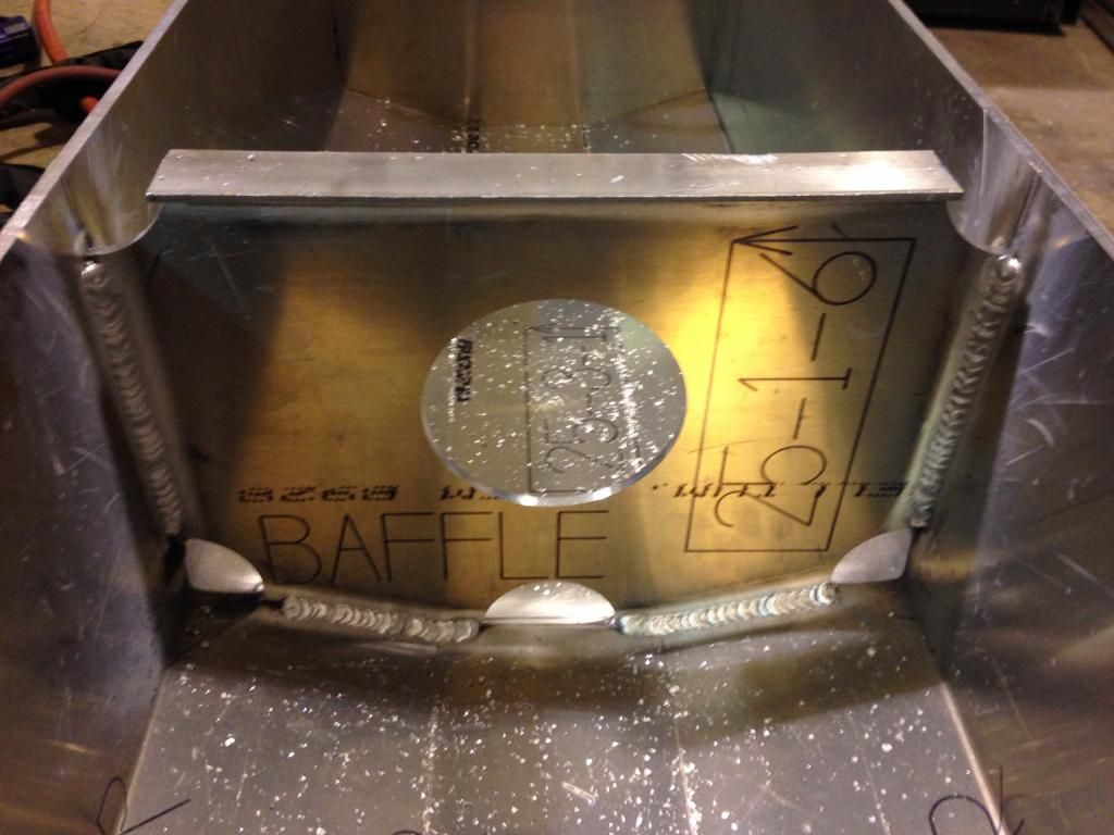
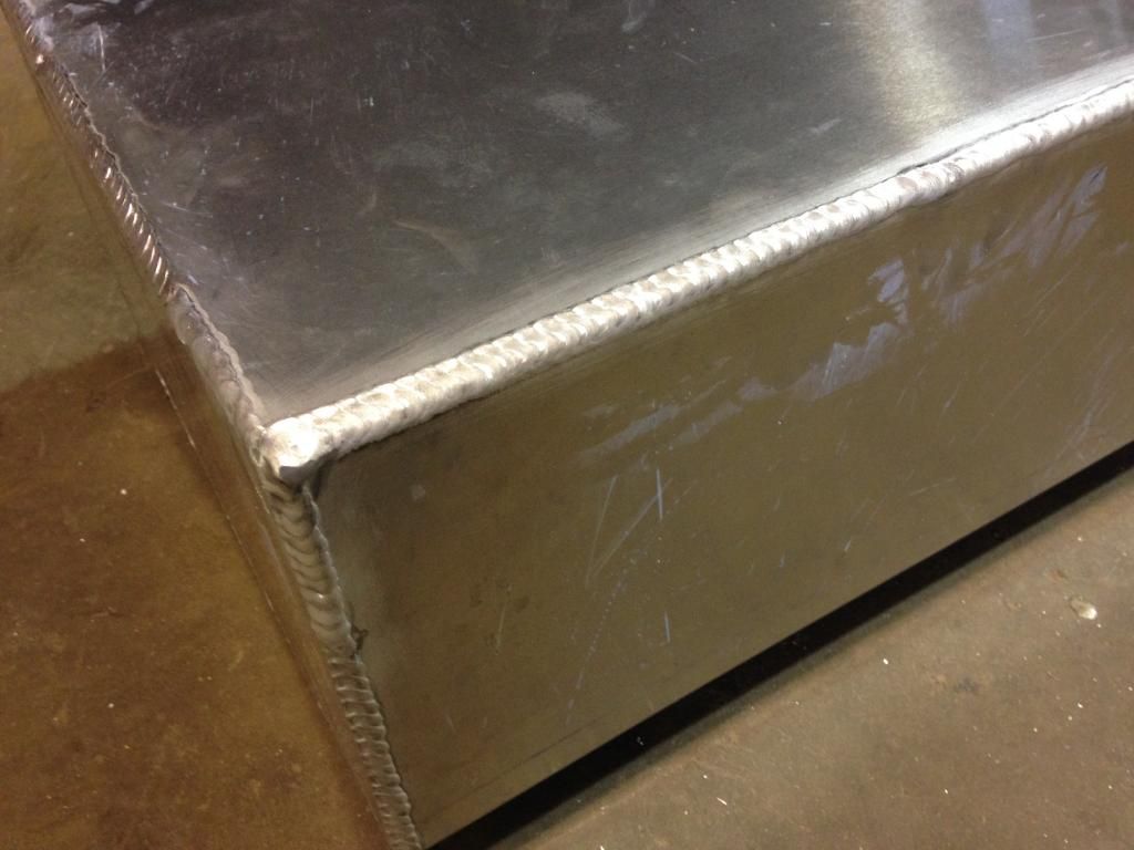
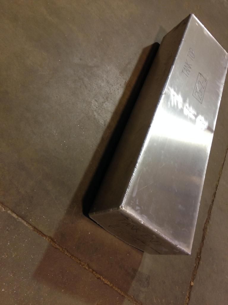
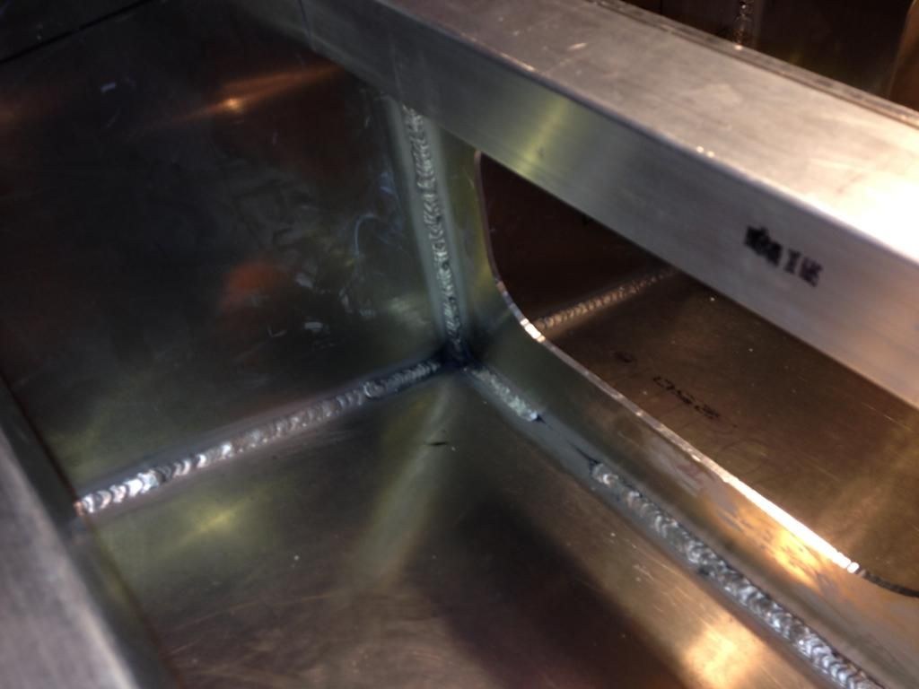
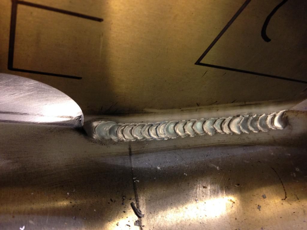
While I waited for tips, hopefully tomorrow :banghead:, I decided to move on to the tank. It isn't perfect, but I'm pretty sure it won't have any leaks. When I get the chance I'll charge it with air and let it sit a couple days.

Center Baffle:
Image

Image

Tank outside
Image

Image


:beer:
kmorin
Donator 08, 09, 10, 11, 12, 13, 14, 15, 16, 17, 18, 19, 20, 21, 22, 23, 24
Posts: 1743
Joined: Mon Aug 18, 2008 1:37 am
15
Location: Kenai, Alaska

Re: Welding Tricky Corners

#8

Post by kmorin »

armor, Welder put the site up to collect and then spread well founded knowledge about his (all our ) passion, well built welded aluminum boats. That's why I'm here, and that's why most others are here. You're welcome for his forethought and energy in putting up this site. And you're welcome to whatever tales of my mistakes you'd like to read.

Yes, welded boat building is an expensive self education. The saying I've heard is " IF you want to make a small fortune building welded boats... first; you start with a large fortune.... then..."

The straight barrel will give some tight space working room, I can see that. One thing is the ceramic pellet tips (spring loaded) will probably fit this extension (?) and I'd never go back to welding with this gun without out them. http://www.mkprod.com/Prod_Access_tips.htm second item down on this link page.

The welds in the mouse holed baffle looks good, I wrap those inside outside so there's less chance of cratering the end of one and the opposite cracking out. The wrap is just two puddles around to the other side through the limber/mouse hole, no effort but worth the tie-in to the other weld.

Outside corners; I TIG all mine but.. I use a TIG Gun that cold wire feeds and allows the TIG weld to happen at MIG speeds and I know that most shops don't have one so the MIG outside corner is the only solution. A very experienced builder that I have yet to successfully lure here to post more of his great work, has a technique for MIGging tanks. He turns way up, super hot, lots of wire and uses a hand guide along the tank's edge to run his torch hand. He welds a 2' seam with this technique in seconds, not many seconds either. The result is a very hot, fully penetrating single pass weld from one end of (most) tanks to the other. I think he calls the guide his 'hog trough' and it gives him an extended reach to guide the entire seam in one pass. Not sure he could this longer tank in one go?

Toe and top of the welds on the tank look good, I usually don't pattern tank weld seams because I'm on the outside corner where 'drag' (pushed but not patterned) welds will give good fusion and I cannot keyhole the weld if I whip the weld. I like to see that keyhole all the way along a tank seam (TIG or MIG) to know my bead is carrying as much back weld as possible. I get this by dragging not whipping in MIG. I can get and keep a keyhole with TIG even patterning the weld because the arc is much shorter and there is no spray or arc cone of filler, only heat and the filler is coming in low.

was the boat router cut (NC) or did you just get your own router out to make those baffles? nice looking cut edges.

Cheers,
Kevin Morin
Kenai, AK
kmorin
ARMOR
Posts: 12
Joined: Tue Aug 19, 2014 2:07 pm
9

Re: Welding Tricky Corners

#9

Post by ARMOR »

Kevin,

I have had a few hours with the straight gooseneck and it is a dream. I actually prefer it over the standard gooseneck. For me, the visibility is much better, especially when working below the knees.

I've seen your tig gun and thought it was a great idea. I generally don't have the patience for tig welding and was able to get one for myself. I'll be honest however, I have yet to find the time to try it out, and I am betting there is a bit of a learning curve. For now, I'll stick with mig as much as I can. The boat was NC router cut by Alaskan in Seattle.

:beer:
Post Reply Previous topicNext topic