
Tfitz, weld some top and bottom scattered along the sheer, fit in between the tacks leaving the tacks full size longer- stopping at the tack. Then when you gouge the tacks taken (cup both together) the ends of the first pass welds too. This shortens the time when the tacks are thinned for welding, and makes the first passes fit in shorter spaces compared to the final passes.
I'd have used 0.045" to tack; just crank it hot and slow the wire, anything '35 will do '45 will do in this case; better. It's a matter of adjustment for the tack instead of weld- so the wire to voltage ratio combined with time is not going to end up with a good solid weld but in a short time will spray hot, melt and then stop, leaving a small hot faced weld to stick on both sides with the least build up.
Looks like its on? what's to stop some wider tacks being gouged down small and compact for the final welds?
Still need a small toe rail in my view! 1-1/4" x 1/4" flat bar tacked then stitched to the break from horizontal to 45 degree at the deck line. This walk-around may be too narrow for that along the house? but it would sure be comforting to me walking forward to have that small vertical bar for the boot toes.
Cheers,
Kevin Morin
Kenai, AK
24' DYI alloy remodel
-
kmorin
- Donator 08, 09, 10, 11, 12, 13, 14, 15, 16, 17, 18, 19, 20, 21, 22, 23, 24
- Posts: 1743
- Joined: Mon Aug 18, 2008 1:37 am
- 15
- Location: Kenai, Alaska
Re: 24' DYI alloy remodel
kmorin
Re: 24' DYI alloy remodel
I turned the volts up by 1 and the wire speed down about 10% and the 3/64 wire did do ok tacking the lower rub rail on. The rub rails look good to me on the boat but Something about them looks out of proportion or something not sure what it is. Maybe I'm just not use to it yet. That toe rail thing really seems to bother you more than me but I know from experience that I need to listen to you so if you want me to fix that I will but you have to come up with a better idea than weld a piece of flat stock vertical to the edge! How about a half pipe "rib" that runs along the 45deg to flat deck break? That would keep the edges nice and round and still give a toe hold...sorta / kinda. I think I'm going to make a new weld on HD aluminum rail so maybe I will incorperate a real toe rail into that? But to me, my priorities are #1 getting my floor raised and floor supports / hull beefed up.#2 figuring out how I'm going to raise my floor 9" and still access my engine and hull for maintenance. #3 order new or fix my old gas tanks. # 4 cut my cabin in half and extend it 2' back. I could go on and on but it makes my head hurt. So the toe rail deal seems pretty low on my list of priorities right now. I'm glad this stuff is fun because it sure is allot of work. 
- Attachments
-
-
Re: 24' DYI alloy remodel
What do you think of this idea for a toe hold? The edge around the entire boat is dangerously slippery. With these 1/2" half pipes I could put all the way down port and starboard sides and paint or sticker the abrasive, black anti skid material to the top of each 6" pipe. It would drain, not be a sharp edge and add a distinked black, dashed line to the boat looks. I don't know if it would be a good or frankienstien type line but garranteed to be unique among boats in the harbor. I think with the noticeable bump the 1/2 pipe would give you along that slippery edge and the abrasive strip your footing would be good bow to stern! What do you think? Would you stow the hook on a flat fish trip for me on this boat if I came to Kenai? Or would this only be a good idea if I was building a Chinese junket boat?
- Attachments
-
-
-
-
kmorin
- Donator 08, 09, 10, 11, 12, 13, 14, 15, 16, 17, 18, 19, 20, 21, 22, 23, 24
- Posts: 1743
- Joined: Mon Aug 18, 2008 1:37 am
- 15
- Location: Kenai, Alaska
Re: 24' DYI alloy remodel
Tfitz, the welds seem a little wider than needed to me, I try hard to keep those narrow so they pull the sides less than wider welds would/do.
Toe rail, flat bar is better by far than pipe, pipe- even continuous- is a slip hazard, 1" bar is better.
Cheers,
Kevin Morin
Keani, AK
Toe rail, flat bar is better by far than pipe, pipe- even continuous- is a slip hazard, 1" bar is better.
Cheers,
Kevin Morin
Keani, AK
kmorin
Re: 24' DYI alloy remodel
I don't know how to make the welds any narrower with 3/64 wire. If I try to go faster pin holes form and I have to back up half a lap to fill them. If I mess much with the volts or wire speed I risk not have good edge fusion. I could try .035 and see what happens? But if you want to tell me how to do it your going to have to respond soon because I'm headed out to my shop to try and weld another rub rail down tonight. I skip around allot so I see no warpage from heat.
My neighbor and I were looking at the boat drinking a beer in my shop discussing the toe rail delema and decided the small half pipe sections were NOT the way to go. But a continuous, one length 1/2" half pipe with a black anti skid strip down the middle of the 1/2 pipe would look less ghetto. I just can't see that sharp, 1" flat bar running over halfway down the boat an acceptable way to go. I will probably have to slip off and almost drown before I say you are right on this one. But enough thinking about that I need think about narrow welds now.
My neighbor and I were looking at the boat drinking a beer in my shop discussing the toe rail delema and decided the small half pipe sections were NOT the way to go. But a continuous, one length 1/2" half pipe with a black anti skid strip down the middle of the 1/2 pipe would look less ghetto. I just can't see that sharp, 1" flat bar running over halfway down the boat an acceptable way to go. I will probably have to slip off and almost drown before I say you are right on this one. But enough thinking about that I need think about narrow welds now.
Re: 24' DYI alloy remodel
I learned allot tonight and got a rub rail welded down. I started off at the same settings as last night. After a few welds with ok results (photo#1) I must have bumped my wire speed up by accident from 360 to 460. Holy Cow it was time to get up n GO! (Photo#2) I liked it!! The welds went way faster, smother and had flat starts with no pinholes. But it was too hot so backed it off about halfway from where it was and didn't touch the volt setting. Things got easier and better looking in my opinion. They did get a little narrower but not much. Overall I'm happy with the welds even if I did get there by accident
- Attachments
-
- Same welding settings as last night
-
- Wire speed 25% greater
-
- Wire speed about 13% greater than last night
-
- Flat
-
- Overhead
-
kmorin
- Donator 08, 09, 10, 11, 12, 13, 14, 15, 16, 17, 18, 19, 20, 21, 22, 23, 24
- Posts: 1743
- Joined: Mon Aug 18, 2008 1:37 am
- 15
- Location: Kenai, Alaska
Re: 24' DYI alloy remodel
Tfitz, the surface of the too hot welds shows a granulation not a clean ripple, that means you can do one of either side of the coin; turn down power OR turn up wire. Both result in a shorter arc length which is where that granulated surface comes in.
Next if you turn down the power then the heat of fusion drops and the welds' can curl so adding wire is the ticket in this weld as you found out. Next though is the start and stop technique of wrapping the welds.
Ends can be whipped out, the crater will be cut by the carbide tool AND the "back step" start puddle if you add those to your technique?
To do a standalone MIG weld, one that won't be part of a long continuous weld, you'd begin 1 to 2 puddles into the weld zone with the wire point. Then as you pull the trigger, move must faster than welding speed (backward in the weld's orientation) toward the 'real' beginning of the weld. When your wire tip/arc cone is at the 'real' beginning of your weld reverse your direction of travel (again) and begin the weld, COVERING with hot molten weld wire the 'start' that was done 2x the speed of the weld. By learning to move overly fast in these covered start it will not have the same amount of filler the rest of the weld has.
This allows the power supply to get to full weld voltage, the wire to form the arc but these are both done
BEFORE the final weld is actually being applied to the joint. So as you weld, beginning at the 2 puddle right hand position from the start, you'd cover over the small spattered start and have full heat, full wire speed, and regular travel speed to fuse those 'cold start' droplets into the final weld.
This is reversed at the end of the weld where you weld back over the last one or two puddles before releasing the trigger. By welding over the last puddle your crater will form on top of, now down in, the final puddle. This is sometimes called race tracking a weld where there's an image of an oval track like path to the stand alone weld.
Now if the weld will be cut out- start and stops cut to cups with carbide burr in prep for the tie in welds, the last overlap backwards at the stop described above is not needed. Its just more metal to cut out- why bother?
The whip out technique involves timing the trigger finger release, the end of the puddle and the gun's gas cup position. To whip out and leave no crater; begin by snapping the torch wrist (right hand in my description) to the right where the gas cup would then be moved to the left very fast. While that is going on, release the trigger so the contactor drops welding power, AND the gun stops feeding wire all at the same time. What results is a hollow 'smeared puddle' that is pulled, while molten, to the left and it elongates, coats the weld area but leaves no build up.
This is used by most MIG welders in aluminum where they know the weld will be continuous, and it saves some of the burr work to prep another set of welds. The technique is not used on stand alone weld like stitching a long to the bottom or a stitched side rail that will be left intermittent welded. The reason it is used in continuous welds is to reduce prep, you're going to cut out the ends any way. The reason this whipping technique is not used in stand alone chain or stitch welding is the stop end can be a notch or crack location this technique.
Both these ideas are harder by far for me to do with a 1lb. gun than a push-pull which is more compact and ergo-metrically designed. But the techniques do work, can help over all in both types of welds and would help your starts shown above.
The toe rail is not sharp, bar extrusions have a radius- admittedly small- and the slip under the hand rail and off that very narrow (too narrow) deck will result in someone grabbing the hand rail. The injury we most often see is a inter-rib muscle tear or strain. This happens when you're cool, standing around the cabin in oil skins, then go forward and slip. Not warmed by lifting or working to move things your cooled down muscles will tear or strain when you reflexively try to hold yourself in an overhead grab to the hand rail as you head hits the cabin or the thigh hits the deck edge. Also most folks hit something of the boat with their head when the slip under the hand rail and can't hold themselves on the boat.
One factor we've seen that doesn't seem to get much consideration is that narrow side decks like this force the bow man to move foot in front of another. We can't walk with our balance of feet side by side. So if the outboard slip is made by the inboard leg... well; just climb up there and give a little walk on that and see what kinds of movements could happen?
Wouldn't say it if I'd not seen it, good non slip on the narrow deck will be very important given the design of the boat. Sure don't want you to have to learn this the way others have!
A toe rail suspended above the deck line incorporated into the hand rail/bow pulpit stanchions may be a better alternative? Anyway, the narrow deck combined with narrow hull will give a rolling movement that may require a little attention to safety when moving forward on this boat.
Cheers,
Kevin Morin
Kenai, AK
kmorin
Re: 24' DYI alloy remodel
You explain things so well I "see" exactly what your talking about. Thank you! But the sad thing is not to long ago you described this to me already, in less detail, but I understood it and I thought I was doing just what you said. But I my whip action must not be fast enough to keep the starting weld material down. But I will focus on that tonight. I have lots of continuous welding to do to get this technique dialed in. I'm going to start the upper rub rail tonight.
Maybe the way to do this toe rail is incorporate an above the deck bar between the bow handrails then transition into an edge like I'm thinking as it passes by the cabin toward the stern. I would never leave the cockpit and step out on the narrow deck to go forward with anything less than a death grip on the handrails. My last boat was the same way so I guess I'm use to it.
Maybe the way to do this toe rail is incorporate an above the deck bar between the bow handrails then transition into an edge like I'm thinking as it passes by the cabin toward the stern. I would never leave the cockpit and step out on the narrow deck to go forward with anything less than a death grip on the handrails. My last boat was the same way so I guess I'm use to it.
Re: 24' DYI alloy remodel
I have one upper rub rail about 1/2 continuous welded down and I'm pretty satisfied with how the welds are coming out...but what do I know. I wasn't even sure how to load the spool gun a few weeks ago so please tell me what I can do to make my welds better. I grind out the starts and finishes of each connecting weld, wire brush just before welding, clip the tip of my wire before each weld and try to whip in and out like you described earlier. I actually have an easier time making the overhead welds look the best to my surprise they are easier for me. The bad angle photos show the stern rub rail and how the swim deck is limiting my angle to make a good weld. Today I got my new spool gun flex tip and it doesn't help me as much as I had hoped. Any ideas how to get the bottom of the rub rail welded? And one last question. My new "Shark eye" LED navigation lights arrived and they have a rubber sealing gasket under the stainless fixture. I don't like rubber after seeing what the rubber rub rail did to my boat. What is the solution to that? I sure am enjoying this process of learning to weld aluminum and this boat project. I work late every evening and I only stop because I'm exhausted. I seem really slow at this, there is allot of steps to do before each weld! I would be real curious how fast or what short cuts "real" welders do to get it done.
- Attachments
-
- Top side rub rail
-
- Top side rub rail
-
- Bottom side rub rail
-
- Top side rub rail
-
- Top side rub rail
-
- Bad angle
-
- Bad angle
-
- Rubber gasket sealed
-
kmorin
- Donator 08, 09, 10, 11, 12, 13, 14, 15, 16, 17, 18, 19, 20, 21, 22, 23, 24
- Posts: 1743
- Joined: Mon Aug 18, 2008 1:37 am
- 15
- Location: Kenai, Alaska
Re: 24' DYI alloy remodel
Yes, this is true for most welders in my experience, they expect overhead MIG to be a problem only to find it is actually an easy and very controllable weld. The welds look good, if I were tuning I'd add just a touch of wire, OR just put the gas cup a little closer to the work to shorten the arc bit. I'm basing those remarks on the presence of some side spray droplets that you showed in the posts above -also.Tfitz wrote: I actually have an easier time making the overhead welds look the best to my surprise they are easier for me.
Then I think you cranked the wire speed and the welds got cleaner. One other remark about overhead welding is that the weld arc and wire arc cone are more easily visible without craning the neck quite so much. Last, not being bound up with your elbows more free and a hand to drag/guide/follow the hull this weld leaves better muscle movement than a more constrained version where your elbows are closer to the body and the torso turn makes the torch follow a circle along the weld instead the nice straight(er) line that can happen more easily overhead.
To weld where the position is 'too tight' to get the gun, you can bend the contact tip, if you're using a longer copper barrel type (?) and make sure that you mark the bend to the tip, when the the tip is screwed tight to the torch extension. This bent tip can help get that last curve upward of the wire into this bad angle joint shown. It is a pain in the stern, no matter what you do, further the tread plate embossing/diamonds will make dragging the torch 'lumpy' so the weld is a real challenge. I might simply stitch that section? Lay the torch on its side as much as possible, the roll it up the small angle that the gas cup allows, mark the 12:00 side of the tip's screwed in position, then bend the tip a little and screw it back in, feed some wire, trim it to the 1/4" stick out, judge if you can bend a bit more? repeat. Without taking off the deck shown, that's about all I can come up with to suggest welding this tight spot.
Cut the 1/2 pipe corners (stern joint shown) out to a 45 (each side) and put a 3rd piece in between the two long rails' ends- as trimmed. This will give a mitered outside joint instead of the pointed joint now fit. The edges of the three pieces should be beveled 70% of the thickness and then the existing extrusion blown out of chips from the opposite ends, before the tack up happens. This 'strip' piece of pipe that fills between the two mitered 1/2 pipe ends can be very slightly flattened tip to tip (make it just a few percent wider) and fill the joint between the two half pipes cleanly. The tight fit, but beveled open outside corners, will allow a MIG weld, hot & fast, down hill-pushing the bead. Then that bead can be sanded clean, making a reasonably attractive corner finished with 3M buffing to a nice looking joint with good strength.
regarding the lites' install; I agree that a rubber gasket which retains water in a film will promote corrosion. If possible I'd cover the area to be mounted over, with primer? To do this I'd etch, coat with Allodyne, then primer them mount- talk about long time to prepare !!! yes I agree. Another method I've used is to tape off the area where the mount will got, use the mount to put in a pattern, use an offset knife/razor with side to side spacer so the blade cuts an outline in the solid taped off covering the exact shape of the mounting base PLUS the offset. Then pull that area of tap out of the middle leaving the rest of the area around the mounts taped covered.
Then I cover the mounted object's upper, visible services with tape too. Then I set the mounted object on the bench and lay the razor on some plate 3/16" (?) and trace around the base's vertical side so I cut off a uniform strip of tape along the mounted hardware's base. So if the mounted object were now put on the hull, screw holes lined up and all, there would be a uniform strip of bare hull surrrounding the uniform strip of the mounted devices base open too.
I'd use 5200 to bed the base rubber to the hull and mount the device with screws and only tighten enough to keep the device base firmly but not 'oil field tight' to the hull. The 5200 if put on carefully (a minor welding art not appreciated by most builders) it will just bulge out the entire base perimeter of the rubber gasket.
Now I take more 5200 and fill the bare strip and seal the devise to the boat's bare aluminum (I prep with sander#1; brush #2; and acetone#3 before this) and then use a rounded stick to 'strike off' the 5200 on both sides of the tape cover. Then let the 5200 sit for a while, I rarely use the 'fast cure' version because I'm not usually in a hurry, and when the 5200 is stiff but not set, pull the tape and you end up with a nice bead of coved 5200 sealing the bar hull and the base so water can't get in.
You asked. I'd also suggest using bolts over screws to mount, and plastic tube sections over the bolt bodies if possible?
I'm not sure if working till tired is good practice, the mistakes in my work seem to go up when really tired so, I'd say staging the work in diminishing demands per task seems like a better evening than going full throttle till you drop. However I'm not longer bullet proof and only have vague memories of that period of time in my life, so old guys probably see this differently than younger more energetic builders.
REmodeling is more work than building since you have to do the work to take apart, recover and clean, set up and prep then weld. The welding is lots of aluminum remodels, including yours, is somewhat more of a pain to do since lots of the sequence of building is not original. The obvious one in this post is your stern rub rail piece's lower weld.
On the other hand, in my experience there are minimum of 8 times the work to get ready in the simplest skiff, and in cabins, brackets, helms stations and other more detailed work I'd move the ratio of prep to weld up to 20:1. It takes two or more days work to get ready for an hours' welding.
What you might not know is the even larger boat builders have only one or two full time welders with a crew of half dozen fitters and helpers to that one torch. There are some builders where the fitter will tack, so the ratios go higher still. When I built full time I could weld for two sets of 4-5 fitters each building a skiff side by side in the shop. I had separate torches for each skiff, and one TIG gun to reach between them both, so it is possible to tack, with one group while another is fitting and then reverse that; then weld out what was done in a mornings work in the first hour after lunch. Just some references, the ratio of all types of work before welding is high. But then in a dead plants that's the same for 'glue up' or in plastic/"frozen snot" its similar each of the boat building processes have the prep and that one key process and the ratios are very similar.
Work looks good, coming along, I'd suggest an evening walking around with some refreshment and stop and look at different items just to get some perspective. Looks to me like you've come no short distance in a pretty short time?
cheers,
Kevin Morin
Kenai, AK
kmorin
Re: 24' DYI alloy remodel
Thanks Kevin that means allot to me coming from a guy like you. I'm going to just keep plowing away at this and try to finish the rub rails this weekend then it will be time to move inside the boat to figure out my floor height and lay out as well as the gas tank configuration. And oh yea...repair all the broken and crappy hull welds and beef up the cross supports. Lots and lots of work ahead but at least I feel like I'm getting my arms around some of these issues now. 
Re: 24' DYI alloy remodel
Your last post didn't give me the crystal clear vision I usually get from your choice of words. So I couldn't quite follow the navigation lights instructions too well. But it seems like the goal is to isolate everything non aluminum from the parent metal? So why not keep it simple and put a layer 5200 between the rubber gasket and the hull. That's it??
I'm not sure I got your idea on the corner either but this should work out ok?
I was trying to figure out a way to speed this rub rail welding job up and then it came to me...Duh?? Instead if 6" welds make 12" welds. And they came out fine! I even did a 14"!! That was a bit of a stretch though but it looked good to me.
I like the way my pulpit turned out. The gussets I added seem to contribute to the "lines" of the boat. The rub rails, and now the pulpit kind of made the boat look like it took steroids and it appears more capable of doing battle on the halibut grounds.
- Attachments
-
- Pulpit beefed up
-
- Rub rails welded down
-
- Corners ready to tack in place
-
- 11" welds
Re: 24' DYI alloy remodel
I forgot to mention the problems I had with welding the stern 1/2 pipe bottom seam. I got 2-3" weld on each end of the underside seam and hit some imbedded corrosion. I could see more corrosion areas ahead of my weld so I quit. Between the bad position and corrosion I figure a bead of 5200 will keep the inside of that 1/2 pipe dry. I welded the top side up with no problems. Nothing structural about The 1/2 pipe it is really just covering the surface corrosion so no big deal in my view
-
kmorin
- Donator 08, 09, 10, 11, 12, 13, 14, 15, 16, 17, 18, 19, 20, 21, 22, 23, 24
- Posts: 1743
- Joined: Mon Aug 18, 2008 1:37 am
- 15
- Location: Kenai, Alaska
Re: 24' DYI alloy remodel
Tfitz, corner is exactly what I attempted to describe.
Longer welds are a good solution, yofish who hasn't posted here much, has some speed welding techniques on weldingweb and shows a fixture he uses to speed up his weld while staying steady.
Bow roller frames give a 'droop nose' look that looks fine when the hull is running with a few degrees upward pitch by the bow, but seems to be a little odd sitting at the waterline. Some entire product lines of boats use the reverse sheer line or 'droop' and running they look fine. In fact they look so poor sitting still most of these plastic boat lines show their boats exclusively in running shots.
As someone who's drawn boats for a long time; its a preference issue. IF the bow has traditional lines cupped and rising sheer, it looks good sitting still but may be too tall to see over the bow running with a bow up pitch. IF the bow is lowered to see over it while pitched up.... then it tends to look a little droopy (in my eyes) while sitting at rest. So the flat sheer is often used in most welded boats to compensate for these two conflicting appearances.
Mounting the lights with a barrier of 5200 is fine but water will get behind it and stand and it will corrode if you don't seal the outer seam of the 5200 to the isolation gasket and metal. That is the technique of taping off, cutting a thin strip and striking off described; to get a film between the rubber and metal AND to seal that outer seam line at the hull but to have it come out clean, coved and uniform- like a high quality weld seam around the base of the light fixture.
Cheers,
Kevin Morin
Kenai, AK
kmorin
Re: 24' DYI alloy remodel
The more I thought about glueing the lower stern rub rail seam the more I didn't want to do it. So I came up with the idea to weld a piece of 1" X 3/16" flat bar to span the corrosion and give me a little easier angle to weld at and it worked well enough that I'm happy with it. And I like at corners too. Photo 1
So I moved inside the boat and the MANEATER made short work of removing all the floor and gas tank supports. Photo 2
Now I'm trying to come up with a workable plan to raise my floor 9" higher from original height and still be able to do Maintaince to the engine. So what if I used 3/16 for the floor and bent a 4 " edge all the way around. Could I get away with not supporting the underside of the floor edge all around the engine to have better access for maintenance. I mean the floor would only be supported at the 22" centers of the crosspieces. And I would religh on the bent 4" edge to support the floor between the crosspeices. Like the cardboard shows (photo 3, 4) the cardboard should actually be 9" higher from where it is now to represent the new floor height. In that corner where the cardboard is shown, I plan to put a drain that will make the deck into a semi self bailing floor. I will make the floor easy to remove for engine Maintaince. The card board templete shown will be like a 3 sided box with 4 inch edge that will capture deck water and make it drain overboard with a through hull pipe drain. Does any of this màke sence to you.? I'm a bad idea explainer
- Attachments
-
- Stern rub rail and corners
-
- Cockpit gutted
-
- 3/16" Floor templete
-
- Engine access
Re: 24' DYI alloy remodel
Anyone know of a good source where to buy weldable components to build a aluminum gas tank? Like 90 deg filler necks. And weld in pick up tubes, sending units and vent ports. I just ordered two sheets of .160 5053 and plan to have them TIG welded. Any words of wisdom are welcome.
-
kmorin
- Donator 08, 09, 10, 11, 12, 13, 14, 15, 16, 17, 18, 19, 20, 21, 22, 23, 24
- Posts: 1743
- Joined: Mon Aug 18, 2008 1:37 am
- 15
- Location: Kenai, Alaska
Re: 24' DYI alloy remodel
Tfitz,
while some of the weld in parts available are useful in some designs, many tanks can be made from just pipe & plate.
Draw Tubes can be of 3/8" pipe an that will allow a plastic liner with foot screen to be installed, but I've used up to 1/2' 6061-T6 pipe without problems.
Fill fittings can be done of regular pipe since there are fuel rated hoses that have ID's based on Pipe OD. For example you could use a King Nipple, or turned down and ringed pipe to fit side 2" ID hose OR, you can buy hose that is 2-3/8" ID (also called 2" hose many times) and fit on to the regular OD of 2" pipe.
Vent and Draw Tubes can be fit to 1/2 of a pipe coupler welded to the tank, either flush or protruding, and either straight or Street 90 Els fittings can be used in these locations to keep the tubing close to the tank surface, again depending on design and space requirements.
Sumps if you'll be including them, can be made of simply an inch of heavy wall pipe with a 3/8" plate disc bottom, and a duplicate draw tube for pulling water bottoms out? Not everyone considers sumps important, but they sure do increase tank life if serviced reliably.
Tanks themselves are pretty easily cut to rectangular shape of plate and then tacked edge to edge and TIGged with a keyhole weld on the top. Most of the inside seams, baffles and furniture can be done with MIG inside the tank (not as easily with a spool gun as push pull style due to the gun shape) and TIG outside. That leaves (usually) only the top with a single pass weld.
Mounts are usually done the best by making external plate doublers and the the mounts outside those plates and gussets to support all attached outside the doublers. The reason being, the welds direction to the tank wall may have some crater cracking potential sites, and running vibration may, over time; foster a crack. So the only thing that cracks is the doubler not the tank wall. Of course all depends, again, on the design of the tankage.

Section of a skiff tank plan showing the standard pipe parts and the planned folded material to make the tank.

Regular pipe couplers cut in 1/2 to make surface mount threaded ports to connect fill and vent fittings. The plate doublers are to help stiffen the location of the downcomers so there is no/less potential for load on the top surface. Notice on couple is 'buried' to allow a lower profile fitting installation, the corner coupler is on top of the tank to vent the entire vertical volume without a vent trap? Background welds at the baffle top flange keyhole welds to the top plate.

"keyhole" welding insures the weld of the top to sides, a one sided outside weld, is back welded as fully as possible. I don't think the top will actually come off if the weld is not done to this technique but its not hard to do and is the best method so it should be followed for single pass outside corner TIG welds.
If you have drawings, any form of drawings, that's where to start good tank builds, IMO.
Cheers,
Kevin Morin
Kenai, AK
while some of the weld in parts available are useful in some designs, many tanks can be made from just pipe & plate.
Draw Tubes can be of 3/8" pipe an that will allow a plastic liner with foot screen to be installed, but I've used up to 1/2' 6061-T6 pipe without problems.
Fill fittings can be done of regular pipe since there are fuel rated hoses that have ID's based on Pipe OD. For example you could use a King Nipple, or turned down and ringed pipe to fit side 2" ID hose OR, you can buy hose that is 2-3/8" ID (also called 2" hose many times) and fit on to the regular OD of 2" pipe.
Vent and Draw Tubes can be fit to 1/2 of a pipe coupler welded to the tank, either flush or protruding, and either straight or Street 90 Els fittings can be used in these locations to keep the tubing close to the tank surface, again depending on design and space requirements.
Sumps if you'll be including them, can be made of simply an inch of heavy wall pipe with a 3/8" plate disc bottom, and a duplicate draw tube for pulling water bottoms out? Not everyone considers sumps important, but they sure do increase tank life if serviced reliably.
Tanks themselves are pretty easily cut to rectangular shape of plate and then tacked edge to edge and TIGged with a keyhole weld on the top. Most of the inside seams, baffles and furniture can be done with MIG inside the tank (not as easily with a spool gun as push pull style due to the gun shape) and TIG outside. That leaves (usually) only the top with a single pass weld.
Mounts are usually done the best by making external plate doublers and the the mounts outside those plates and gussets to support all attached outside the doublers. The reason being, the welds direction to the tank wall may have some crater cracking potential sites, and running vibration may, over time; foster a crack. So the only thing that cracks is the doubler not the tank wall. Of course all depends, again, on the design of the tankage.
Section of a skiff tank plan showing the standard pipe parts and the planned folded material to make the tank.
Regular pipe couplers cut in 1/2 to make surface mount threaded ports to connect fill and vent fittings. The plate doublers are to help stiffen the location of the downcomers so there is no/less potential for load on the top surface. Notice on couple is 'buried' to allow a lower profile fitting installation, the corner coupler is on top of the tank to vent the entire vertical volume without a vent trap? Background welds at the baffle top flange keyhole welds to the top plate.
"keyhole" welding insures the weld of the top to sides, a one sided outside weld, is back welded as fully as possible. I don't think the top will actually come off if the weld is not done to this technique but its not hard to do and is the best method so it should be followed for single pass outside corner TIG welds.
If you have drawings, any form of drawings, that's where to start good tank builds, IMO.
Cheers,
Kevin Morin
Kenai, AK
kmorin
Re: 24' DYI alloy remodel
I drills and taps a ½ x 3 x 8 inch aluminum plate to the top of the tank for the air vent, senders, ground and return line plus a spare.
.160 seams thin for a boat fuel tank, but that just me. Are you going to presser test the tank before you install it? Have you thought about what you are going to do about corrosion control, if it going to be a problem.
Ya I know..... I take a simple thing and pick it apart looking for problem areas that may or may not be their. http://aluminumalloyboats.com/posting.p ... f=3&t=5692#
Re: 24' DYI alloy remodel
Your TIG welds are a thing of beauty. I may have to start looking for a machine and try that, looks like fun to me. I don't understand how to use a 3/8" pipe for the pickup tube with a plastic liner with foot screen comment you made? The coupling idea is great and will save me some money. But where do you buy your aluminum or SS street 90 ells and king nipples? Do you usually put tabs on your tanks and weld them down or secure them another way? Why do you take your filler tube to the bottom of the tank? Seems like it could end and just spill in at the top? Do you have a preference when it comes to the type of fuel sending units to use? I see they make a tube style that sound good for boat applications. Those key hole welds look like just a big tack on the top side of the baffle? Looks like about a 1/2" hole you welded through to tie things together?
-
kmorin
- Donator 08, 09, 10, 11, 12, 13, 14, 15, 16, 17, 18, 19, 20, 21, 22, 23, 24
- Posts: 1743
- Joined: Mon Aug 18, 2008 1:37 am
- 15
- Location: Kenai, Alaska
Re: 24' DYI alloy remodel
I'm referring to 1/4" plastic fuel proof tubing (lots of types can be used) and a small inline replaceable screen/filter that can be installed at the bottom to keep the fuel line from picking up 'tank junk' of the different types that form or get inside the tanks. The idea is that a plastic bottom located tube/hose is not rigid enough to stay down where it belongs so using a small bore pipe as the conduit allows the tube to be placed exactly for the draw. Next, at the top- the tube can be left inside a pipe fitting so the tube can be removed to replace the small inline filter/screen of the type you'd find in a chainsaw, or small engine. This makes sort of a hollow plastic handle on a small inline filter screen located on the bottom of the draw tube.Tfitz wrote:I don't understand how to use a 3/8" pipe for the pickup tube with a plastic liner with foot screen comment you made?
[anchor= goto=][/anchor] http://www.buyfittingsonline.com/ these are likely Indian or other lower quality but I've used them for lots of fittings. I'd suggest you investigate passivization solutions to go with all SS fittings. Basically gives all SS a more inert (not totally inert) surface. I've used Gately Stainless in San Fran too, (not sure if they every got a web page?) but, while often higher quality; sometimes the costs are better with the fittingsonline outfit. My LWS is so tuned to what boat builders need they often stock all the fittings from 2" down, well mostly in the warmer months but I've found them willing to bring them if for me at a reasonable margin too.Tfitz wrote:But where do you buy your aluminum or SS street 90 ells and king nipples?
Well you should ask. Note my suggestion is to plan well. I prefer to make removable tanks in my boats, so I rarely weld them in unless they'll be below a welded deck- my reason is if you've got to cut the deck out to get to the tank, and that's true many places, then I might as well cut the tanks out too. But if the tank is removable I prefer to bolt them in when possible. Tabs is a little vague without a sketch, I mentioned mounts on doublers as my preferred methods, I treat tanks mostly like I treat an inboard engine with similar, but in scale, mounts.Tfitz wrote:Do you usually put tabs on your tanks and weld them down or secure them another way?
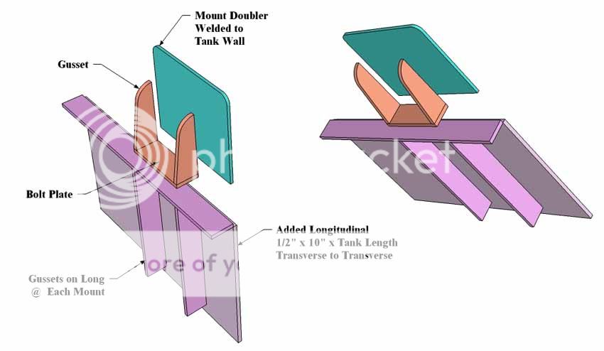
I mount tanks in this general method if below decks where I can get to the hull longs- like an engine.
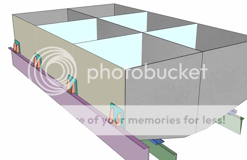
Here's the tank hung from hull longs like an engine. Making the mounts, planning the location and loads and all that are pretty big in my book so I treat loads like fuel like I would a small engine install.
Marine tanks, correctly built, all have fills that lead to the bottom of the tank. The first few gallons then seals the downcomer from the rest of the tank. Now all the gases above the fill level have to go out the vent, and this controls back surging while keeping diesel from frothing. It does the same for gasoline, frothing or foam overflow is now required as part of the vent and fill piping. New CG reg.s to this end are in effect.Tfitz wrote:Why do you take your filler tube to the bottom of the tank? Seems like it could end and just spill in at the top?
Lots of gas docks in the bush will only have 2" fills and pumps. You will probably find out they will flood the deck if you don't have #1 big enough fill downcomers, #2 Big enough vents for that flow rate, & #3 top filled tanks where the primary vent is around the fill area!! (What's that saying about 'peeing into wind'?- "All you get is warm and wet and then it cools off and you still smell like ......?")
Yes- TSIAR Brand: The Skipper Is Always Right! I've put in all the types I've seen, including a bubbler using DP head to gauge some big tanks! I think it depends on your design, budget, location of the tank in the boat, and all those details to make a good choice. I recently used some top mount, SS body, thread in, vertical acting sending units that were very nicely build and installation was just threading their tank top sender body into the half couplers... nice, simple clean, seem reliable and expensive, (but did I mention nicely built and cleanly installed?)Tfitz wrote:Do you have a preference when it comes to the type of fuel sending units to use?
http://www.fisheriessupply.com/sitesear ... earch=true but you can use lower cost, still reliable senders like these as well??
The keyholes onto the baffle flanges were 5/8" elongated and beveled sided holes. The top is 0.160" and smaller holes with vertical sides can 'run' the HighFreq to the side walls instead of the flange top at the bottom of the weld. So welding a keyhole (not "keyholing a weld") its good practice with TIG (MIG too) to bevel the sides of the cutout so the arc can be directed to the very bottom surface fusing the weld's first layer there. Then as circle around filling the hole that critical first layer is a weld to the toe of the top plate and the flat of the flange or backer.Tfitz wrote:Those key hole welds look like just a big tack on the top side of the baffle? Looks like about a 1/2" hole you welded through to tie things together?
Mac; I usually build smaller tanks of 1/8" and have for a long time, no problems if the tank was designed correctly. I know the CG wants them all 1/4" but I've had a few tanks on the 'shake table' in Seattle in the 80's and they all stood up fine. The trade off in tank wall thickness is the panel size of unsupported area. If the number and frequency of baffles needed to get an unsupported area down to achieve sufficient strength becomes so high that the work and overall metal in the tank is too much... THEN I'd make them thicker moving up from 0.125" to 0.160" then to 0.187" and so on. My rule of thumb is the baffle and panels as my guide.
All tanks, air flotation voids/tanks, fuel tanks, oil tanks, water tanks, ALL tanks need to be pressure tested in my opinion. I used to buy the Friday beer if I had leaks that week. (I do realize that shop owners can't buy beer for the shop anymore, but that was our past practice.) The amount of pressure for the test is usually about 3psig. But that also depends on the type of tank. If the tank is an aluminum glycol expansion tank on the engine cooling system, then the test should be at 60psig or above. On the other hand if tank is a little 20gal. tank of 1/8" then 3 psig will find any flaws the head of that tank will force out the lower seams. Most MIG welded tanks leak from cold laps, poor starts and stops and most TIG leaks are weld-end closures done to quickly. "Backing out" the last puddle needs to be done somewhat in slow motion to allow the bead to chill in layers from the bottom up, or it can crater and therefore drip fuel.
Ground straps can be done in many different manners, some used dedicated tapped holes for a SS bolt, others use a padeye with another sacrificial doubler against the copper lug and bolt, and paint the entire lug connection in Aviation Gasket to get it sealed.
Tanks should be stripped INSIDE AND OUT (
I like to paint tanks if possible and since they're most often (in my case) built off the boat, they're more of a bench project than in hull so... they can be painted pretty easily. Etch with acid, while wet with rinse water, coat with Allodyne, let dry put on primer and mount the tank. You can use almost any aluminum epoxy grade primer to coat the tanks and they'll perform well.
Tfitz, I hope this helps in tank planning, if there were an economical way to get them back and forth to the lovely banks of the Chena- I'd do them myself; but shipping would likely make it more expensive than the savings in a little bit of tank welding.
I still think a sketch or plans are in order, the graphics don't have to be all that high level to get the idea out there for discussion. Also I'd take time to tape up a cardboard tank so you can really 'see' what you're planning?
Cheers,
Kevin Morin
Kenai, AK
kmorin
Re: 24' DYI alloy remodel
*********************
Kmorin wrote:
So welding a keyhole (not "keyholing a weld") its good practice with TIG (MIG too) to bevel the sides of the cutout so the arc can be directed to the very bottom surface fusing the weld's first layer there. Then as circle around filling the hole that critical first layer is a weld to the toe of the top plate and the flat of the flange or backer.
*********************
Now that interested..............I've never had good luck getting good penetration when welding the out side corner. I never thought of “BEVELING the out side edges. I will add your information to my welding note book. Thank You
The hardest part of welding aluminum IMO is knowing all the “tricks” some people would call it
common sense.
Tfifz......... If you have not already started a welding note book may I suggest you do and put all of Kmonin information in it. It can be worth it weight in gold when you need the information.
Re: 24' DYI alloy remodel
Mac I do have a little black book that I keep on my welder for recording wire speed and volt settings. Maybe I will add some Kmorin notes too. Kevin I still don't understand the fitting necessary to allow a plastic tube inside 3/8" pipe and transition to fuel line as it leaves the tank. Do you use couplings and reducing bushings to accomplish this or weld it together somehow?? Sorry I can't seem to focus on those crystal clear images you describe.
Photo 1 can you notice the new acid wash clean up? I like the white look. The new crosspiece in photo1 will be bolted in for fuel tank removal and engine maint. access. I added some strength and better support across the keel area. I plan to do a similar support for every crosspiece. I'm grinding / cutting out and rewelding all cracked and real bad looking welds. The builder wasn't too proud of his work to say the least. You can see in the last photo the shape and spot where my 65 gallon gas tanks go. 48" L x 26 W x 17 hi side x 11.5 short side. I sure appreciate all the gas tank info Kevin you definately educated me on a few things that would have cause me backside pain.
Photo 1 can you notice the new acid wash clean up? I like the white look. The new crosspiece in photo1 will be bolted in for fuel tank removal and engine maint. access. I added some strength and better support across the keel area. I plan to do a similar support for every crosspiece. I'm grinding / cutting out and rewelding all cracked and real bad looking welds. The builder wasn't too proud of his work to say the least. You can see in the last photo the shape and spot where my 65 gallon gas tanks go. 48" L x 26 W x 17 hi side x 11.5 short side. I sure appreciate all the gas tank info Kevin you definately educated me on a few things that would have cause me backside pain.
- Attachments
-
- Photo #1 my new Removable crosspiece
-
- Photo# 2 my support improvements
-
- As found crosspiece support
-
- As found
-
- 65 gal Gas tank location
-
kmorin
- Donator 08, 09, 10, 11, 12, 13, 14, 15, 16, 17, 18, 19, 20, 21, 22, 23, 24
- Posts: 1743
- Joined: Mon Aug 18, 2008 1:37 am
- 15
- Location: Kenai, Alaska
Re: 24' DYI alloy remodel
Tfitz,
3/8" or 1/2" pipe butt welded to the bottom of a 1/2 coupler of 1/2" pipe. The 1/2 coupler is welded to the tank top, either on a doubler or surface of tank. The plastic is inserted into the pipe with the small engine inline strainer/filter/screen and the plastic pipe/tube stops at the bottom of the 1/2" pipe coupler. The SS conversion to tube/hose/pipe fitting is 1/2" MNPT and threads into the 1/2" coupler, the plastic tube is pretty snug fit to the fuel draw pipe, (check size matches prior to purchase) and the pull on the fitting at the top comes up the plastic fuel tube but through the strainer/inline screen.
Etch looks like it cleaned up the bilge. Not sure how the deck will meet the topsides? I'd tend to cut all the side frames off at deck level, and replace them above once the new deck is welded out to the topside? Not sure how this will work with all the clutter of the original framing?
Fuel tanks can be welded in if the deck is welded over them? if you're having tank trouble and have to lift the deck you're sure going to be cutting anyway, no more work to cut out the tanks. Bolting them in isn't really worth the time if the deck is welded over them?
If I were mounting the tanks as I think you describe them, I'd add a set of end brackets integrated into the transverse frames and rely on two along one of the nearest hull longs, and perhaps a 'bed' type bracket outboard at the chine. Do the tanks span two xverse frames or are the frames (which don't appear to be) 4' apart? Does the plan call for the tank to be fit inside the xverse frame openings shown? Just trying to get a clear pic of the plan.
Mac, I don't bevel the pure outside corner welds- tank top edge seam shown. They are gapped a bit at the root face, they're not tight edge-to-edge in tack-up when there will be a keyhole carried to insure inside backweld penetration. The bevel I mention is in the inner sides of the pocket/keyhole/plug weld plates' cutout- so the arc MIG or TIG doesn't wander or 'bridge' to the sides of the 'well' of the plug type weld. Just wanted to clear that up in case I wasn't clear in the first post.
Back to tanks, I think we've gone over them a few times here so searching for that topic in posts would probably be time well spent. One thing to mention that I've seen cause some problems is post welding cleaning out the inside of tanks. They're usually MIG welded inside as back welds. That leaves MIG soot and rinsing that out is important because the soot will wash out in the gasoline, and is so fine it will coat a Racor 'closed'. The film of soot is made up of such fine particles that they will lap one another and cover the filter element like paint. So, cleaning after the welding and testing is done, I think is very important.
I etch tanks in most cases, after welding, but will sometimes buff the mill scale before building. If I've welded inside with MIG, regardless if etched or not, I will put acetone in the tank, roll it around and empty it out. Then I'll add acid and (re) do the etch and rinse that out with water and soap several times, then I'd put some gas in and roll the tank and THEN let it air dry. Then I'd install in the boat, but the level of effort to get the MIG soot out is hard to overdo- just my experience with a boat running a 1/2 mile out into Captain Cook's Inlet and the engine stopped dead with a totally black covering on the filter element eliminating fuel to the engine!
Cheers,
Kevin Morin
Kenai, AK
kmorin