
Old and gray and forgetful NOTICE: If you'd asked me, I'd have told you that this post was already here? I thought, evidently wrong as usual, that I'd moved this entire discussion from Metal Boat site(s) over here where it would make some sense? The steel boat sites that I used to frequent did discuss aluminum but not like we do here, so having removed my posts elsewhere I'll post this here where it may help someone on their own project? [I can't find it (here) but if someone does know where I've already posted (?) then, please let me know and I'll edit that post.]
I've discussed with a lot of owner/builders what "to do" about cabins, pilot houses, dog houses, weather helms, all terms used to describe small cabins on small boats. Few more difficult design projects exist in my experience drawing small boats than to make a stand alone or walk around cabin look well integrated to the boat.
Most of my cabins have ended up looking like something off a corn combine, functional and industrial not very 'boat like' or nautical. I'd like that to be different but its not. That doesn't mean you can't draw something more imaginative or with more attractive proportions for your own boat, its just the sad truth of my work. I'd prefer not to refer to my own designs as 'agricultural' but I do admit that I've not been able to draw a really nice cabin to go with a few sheer-lines that still remain attractive in my eyes, years after they're built.
I have yet to see a stand-up house or weather helm that looks genuinely appealing to my eye, but as with all things; "beauty is in the eye of the beholder" - we all like different lines and proportions, some find one look or design appealing and his next door neighbor doesn't care for it at all.
So this thread won't be able to help you with the best looking designs, and it won't explore very deeply all the preliminary sketches that will make your cabin project look the best. It has to be the readers' understanding that since the cabin has to suit you..... you have to draw or copy the image of the cabin you want. I'm going to explore how anyone with welding skills and some aluminum working experience can design and build a stand alone/walk around cabin for a boat.
Next point as introduction is based on the old saying that 'there's more than one way to skin a cat' -not that I've actually met anyone that has skinned a cat; this method could be changed in countless ways to improve it for your use. My intent is not to try to claim the last word in this area of many boats- instead; I'm giving a basic "how too" .... so you have something to rely on if you're
going to work on your boat to build a closed in helm.
Last, in way of introduction, most of the time I use illustration sketches to help my limp writing as I describe the ideas being presented. In these images I try to color different parts different colors so the parts are not all shades of gray. Being aluminum colored makes it hard to 'see' what pieces are fitted/formed/fabricated together; if you realize I'm not making a paint scheme suggestion in the sketches I think it helps to get the ideas across if the parts are different colors as well as different shapes?
This thread is intended to give a proposed method to make welded aluminum pilot house for those who are at that stage of their build or modifications.
Cheers,
Kevin Morin
Kenai, AK
Pilot House; Design-Build
-
kmorin
- Donator 08, 09, 10, 11, 12, 13, 14, 15, 16, 17, 18, 19, 20, 21, 22, 23, 24
- Posts: 1743
- Joined: Mon Aug 18, 2008 1:37 am
- 15
- Location: Kenai, Alaska
Pilot House; Design-Build
kmorin
-
kmorin
- Donator 08, 09, 10, 11, 12, 13, 14, 15, 16, 17, 18, 19, 20, 21, 22, 23, 24
- Posts: 1743
- Joined: Mon Aug 18, 2008 1:37 am
- 15
- Location: Kenai, Alaska
Re: Pilot House; Design-Build
To begin I'd offer opinions on some basics based on my experiences as references for your planning. I think its best to start with a 'box' that you cabin will fit into? The box has beam/width, the cabin top or height and the length dimensions that you can draw to scale of use CAD to make a box that will contain your design.
The size of the boat is going to have the most influence on the cabin, especially the beam. If the chines are 5' wide, 6' or 7'- then I'd say that the deck edge will be just a bit wider than that dimension; so the width of the house is this deck width, minus twice the walk around space?
How much space is needed to walk around the cabin? If you're a heavy displacement, old, broke down welder like me, at least 12" of deck space is probably the minimum and 18" would be nice but that would mean the cabin were only 22"-28" full width on a 5' chine hull.
Going around the width dimension a few times, maybe chalking the shop floor or putting some chairs next to the desk and walking between them is worth the time. The wider the chines/deck the wider the cabin can be while still allowing walking space between the topsides or guard deck and the cabin sides.
Next is the height of the cabin top, I built a skiff with a brother-in-law who is short like me and every tall friend who's gone on that boat has cussed us for out lack of consideration. On the other hand, its very comfortable for everyone in the family so you'll need to make plans for this second critical dimension with an eye to the crew too!
A reminder that most of the skiffs with stand up helms have a very disproportionate 'outhouse' looking appearance helm due to the sides heights compared to the top of the helm structure. This is one of the main challenges in my view of trying to make a skiff look good with a helm. (Some of the most attractive solutions are to provide a 'sit down' helm where the sheer and the cabin top lines are more closely aligned, vertically, and therefore they look better.)
Last but not least, is the fore and aft distance or length of the cabin structure. This can be as short as just 'wings' or spray shields along side the helm or console and it could be long enough for an entire group of 6 to stand and sit in the cabin. Again this is a design decision for the owner builder to make based on the used of the boat and its weather helm structure. So we could say that the minimum was as T-top & windscreen and the max is (say) a 12' long full cabin for a the entire crew to sit for coffee while underway?

Here is a stand up helm that I did for a skiff a few years past. The skipper wanted 6'2" in the centerline of the cambered top, a 14" deck space on both sides, and a four person cabin. Two seated at the helm or dash, and two standing or sitting behind them max occupancy. The cabin needed a sliding lockable door/hatch/passageway and if possible it shouldn't look like it was built for agricultural purposes.
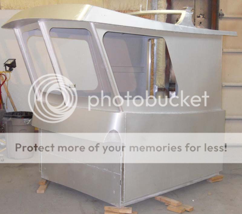
How did it work out? Well it sure is tall, even with all the work (4x the "needed" labor) the curves didn't soften the lines that much. The cabin is a hard design job in my opinion and even with the cut and curved, then welded lines in this cabin making a stand up helm fit the boat and look good is a challenge.
You'll probably see the brow is curved to try to make that flat line more like the sheer? There's a break in the cabin sides that were originally going to be use for a hand rail mount but that was later deleted. The break was more than a few hours of work to cut and fit just to get a line on the cabin that was curved like the sheer.
Above we've talked about the 'box' or rough dimensions of beam, height and length, once those are drawn; planning can continue.

This stand up helm only had three sides and is owner designed and built in a Glen-L/Hankinsen Chinook design. The surfaces are more simplified, the shapes are all much smaller due to the size of the boat. Regardless of your boat size and design complexity, I hope to give some ideas about how to plan your own cabin structure as we move along here.
Cheers,
Kevin Morin
Kenai, AK
The size of the boat is going to have the most influence on the cabin, especially the beam. If the chines are 5' wide, 6' or 7'- then I'd say that the deck edge will be just a bit wider than that dimension; so the width of the house is this deck width, minus twice the walk around space?
How much space is needed to walk around the cabin? If you're a heavy displacement, old, broke down welder like me, at least 12" of deck space is probably the minimum and 18" would be nice but that would mean the cabin were only 22"-28" full width on a 5' chine hull.
Going around the width dimension a few times, maybe chalking the shop floor or putting some chairs next to the desk and walking between them is worth the time. The wider the chines/deck the wider the cabin can be while still allowing walking space between the topsides or guard deck and the cabin sides.
Next is the height of the cabin top, I built a skiff with a brother-in-law who is short like me and every tall friend who's gone on that boat has cussed us for out lack of consideration. On the other hand, its very comfortable for everyone in the family so you'll need to make plans for this second critical dimension with an eye to the crew too!
A reminder that most of the skiffs with stand up helms have a very disproportionate 'outhouse' looking appearance helm due to the sides heights compared to the top of the helm structure. This is one of the main challenges in my view of trying to make a skiff look good with a helm. (Some of the most attractive solutions are to provide a 'sit down' helm where the sheer and the cabin top lines are more closely aligned, vertically, and therefore they look better.)
Last but not least, is the fore and aft distance or length of the cabin structure. This can be as short as just 'wings' or spray shields along side the helm or console and it could be long enough for an entire group of 6 to stand and sit in the cabin. Again this is a design decision for the owner builder to make based on the used of the boat and its weather helm structure. So we could say that the minimum was as T-top & windscreen and the max is (say) a 12' long full cabin for a the entire crew to sit for coffee while underway?
Here is a stand up helm that I did for a skiff a few years past. The skipper wanted 6'2" in the centerline of the cambered top, a 14" deck space on both sides, and a four person cabin. Two seated at the helm or dash, and two standing or sitting behind them max occupancy. The cabin needed a sliding lockable door/hatch/passageway and if possible it shouldn't look like it was built for agricultural purposes.
How did it work out? Well it sure is tall, even with all the work (4x the "needed" labor) the curves didn't soften the lines that much. The cabin is a hard design job in my opinion and even with the cut and curved, then welded lines in this cabin making a stand up helm fit the boat and look good is a challenge.
You'll probably see the brow is curved to try to make that flat line more like the sheer? There's a break in the cabin sides that were originally going to be use for a hand rail mount but that was later deleted. The break was more than a few hours of work to cut and fit just to get a line on the cabin that was curved like the sheer.
Above we've talked about the 'box' or rough dimensions of beam, height and length, once those are drawn; planning can continue.
This stand up helm only had three sides and is owner designed and built in a Glen-L/Hankinsen Chinook design. The surfaces are more simplified, the shapes are all much smaller due to the size of the boat. Regardless of your boat size and design complexity, I hope to give some ideas about how to plan your own cabin structure as we move along here.
Cheers,
Kevin Morin
Kenai, AK
kmorin
-
kmorin
- Donator 08, 09, 10, 11, 12, 13, 14, 15, 16, 17, 18, 19, 20, 21, 22, 23, 24
- Posts: 1743
- Joined: Mon Aug 18, 2008 1:37 am
- 15
- Location: Kenai, Alaska
Re: Pilot House; Design-Build
The terms dog house, weather helm, pilot house, stand up cabin, and others are used referring to a group of shapes, not all identical but like the word 'dory', in boating language, different people use the term for different boats in different locations. I'm going to use cabin now, to simplify the wording and below I'd like to introduce other terms.
These terms are NOT 'right', they're not the only word for the part of piece I'm describing they're just a set of terms I'll use as I write. Lots of times reading online, I can clearly see various posters using terms that each considers to mean something the other person doesn't seem to 'get'. So if you have different words to describe these pieces of design ideas, please don't hesitate to add to the wording here?
The Deck of a boat is a surface exposed to the elements (not always uncovered) but that surface becomes a Sole when you put in in a cabin! But in welded skiffs, many times the cabins we're discussing are welded directly to the deck -does that mean the deck became a sole inside the cabin? and if the cabin is only three sided -what then?
I hope this helps readers to see that my attempt to define terms will hopefully reduce confusion in the thread? A good nautical terms list might be helpful if the labels for parts are not clearly understood, but aluminum boat 'parts' do get called by their other materials boats' forerunners.

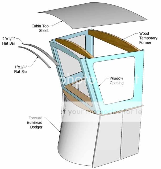
The top of the cabin is the top, the ball cap like visor at above the windows at the forward end is a brow. Glass windows are mounted to the windscreen even if the sides and after bulkhead may screen wind too. So the term "forward or side panel" may be used to discuss the windscreen materials because we're talking in terms of welded aluminum building. I ofter refer to the entire layer of panels on edge above the lower panels as the window band, and the windscreen is the forward panel in that horizontal organization of the cabin.
The vertical structural members in the windscreen structure are Struts and the cabin corners at the height of the windscreen level may be called struts too? In the model above, the bend on the edges of some thin plate, forward and side panels, are fit together and welded forming a welded angle strut at the corners of this simple cabin.
In the following illustrations I've used a series of 'pizza pans' as building blocks. The reason to use this method is to create a light wt shape that is strong compared to its wt. and to reduce as much as possible for the newer builder, welding distortion from internal framing element needed to stiffen the thinner materials of most cabins of this type.
So a note about welding frames to thin materials. I use the term thin for 1/8" (0.125", 3mm) and thinner. I call material thicker than 1/4" (0.25", 6mm) plate and sometimes I'll use plate or sheet for the terms instead. I'm not sure where these terms of use are really defined as I've read lots of articles with different terms. I'm suggesting that most smaller cabin structures are adequately built of 1/8".
Welding edges is somewhat different in terms of distortion than welding 'in the field'. Edges are more often solid welds, or continuous welds, while framing inside a cabin is usually 'stitched' or intermittent welded in a pattern that holds the frame to the skin of the cabin but is not continuous.
Small short welds in proportion to the thickness of the 1/8" house lower topsides or window band panels- to attach framing to these panels is often put in too wide, or, too big in cross section and not proportional to the thickness of the materials. This usually results in a large bulge on the outside call 'print through' and also contracts the entire panel surface causing wrinkles or waves.
So one of the reasons to (design &) build of bent 'pizza pans' is to allow the press brake to put strain hardened edges on the cabin's building blocks so there is little or no interior framing required to be welded in the middle of the various panels or.... 'in the field' of those panels.
Here is a smaller three sided cabin where no framing is needed except one horizontal bar (brown) that ties the lower panels' top edges to one another and provides a base for the upper panels to sit upon.
Each panel's edges are welded to the adjoining panels' with vertical down butt fillets or a horizontal T fillet so there are not side wall framing elements beyond the edges of the pans. True also in the window band these window cutouts can be done before or after the tack and weld of this model of cabin. The edges of the cutouts are "protected" from the welds of the pans' edges by the press braked edges.
OK, I've tried to define terms, given a basic idea of how to create the planning box, shown a few examples of this idea of a building-block cabin of bent pans from thin materials so I'll move to some examples of this type of construction.
Cheers,
Kevin Morin
Kenai, AK
These terms are NOT 'right', they're not the only word for the part of piece I'm describing they're just a set of terms I'll use as I write. Lots of times reading online, I can clearly see various posters using terms that each considers to mean something the other person doesn't seem to 'get'. So if you have different words to describe these pieces of design ideas, please don't hesitate to add to the wording here?
The Deck of a boat is a surface exposed to the elements (not always uncovered) but that surface becomes a Sole when you put in in a cabin! But in welded skiffs, many times the cabins we're discussing are welded directly to the deck -does that mean the deck became a sole inside the cabin? and if the cabin is only three sided -what then?
I hope this helps readers to see that my attempt to define terms will hopefully reduce confusion in the thread? A good nautical terms list might be helpful if the labels for parts are not clearly understood, but aluminum boat 'parts' do get called by their other materials boats' forerunners.
The top of the cabin is the top, the ball cap like visor at above the windows at the forward end is a brow. Glass windows are mounted to the windscreen even if the sides and after bulkhead may screen wind too. So the term "forward or side panel" may be used to discuss the windscreen materials because we're talking in terms of welded aluminum building. I ofter refer to the entire layer of panels on edge above the lower panels as the window band, and the windscreen is the forward panel in that horizontal organization of the cabin.
The vertical structural members in the windscreen structure are Struts and the cabin corners at the height of the windscreen level may be called struts too? In the model above, the bend on the edges of some thin plate, forward and side panels, are fit together and welded forming a welded angle strut at the corners of this simple cabin.
In the following illustrations I've used a series of 'pizza pans' as building blocks. The reason to use this method is to create a light wt shape that is strong compared to its wt. and to reduce as much as possible for the newer builder, welding distortion from internal framing element needed to stiffen the thinner materials of most cabins of this type.
So a note about welding frames to thin materials. I use the term thin for 1/8" (0.125", 3mm) and thinner. I call material thicker than 1/4" (0.25", 6mm) plate and sometimes I'll use plate or sheet for the terms instead. I'm not sure where these terms of use are really defined as I've read lots of articles with different terms. I'm suggesting that most smaller cabin structures are adequately built of 1/8".
Welding edges is somewhat different in terms of distortion than welding 'in the field'. Edges are more often solid welds, or continuous welds, while framing inside a cabin is usually 'stitched' or intermittent welded in a pattern that holds the frame to the skin of the cabin but is not continuous.
Small short welds in proportion to the thickness of the 1/8" house lower topsides or window band panels- to attach framing to these panels is often put in too wide, or, too big in cross section and not proportional to the thickness of the materials. This usually results in a large bulge on the outside call 'print through' and also contracts the entire panel surface causing wrinkles or waves.
So one of the reasons to (design &) build of bent 'pizza pans' is to allow the press brake to put strain hardened edges on the cabin's building blocks so there is little or no interior framing required to be welded in the middle of the various panels or.... 'in the field' of those panels.
Here is a smaller three sided cabin where no framing is needed except one horizontal bar (brown) that ties the lower panels' top edges to one another and provides a base for the upper panels to sit upon.
Each panel's edges are welded to the adjoining panels' with vertical down butt fillets or a horizontal T fillet so there are not side wall framing elements beyond the edges of the pans. True also in the window band these window cutouts can be done before or after the tack and weld of this model of cabin. The edges of the cutouts are "protected" from the welds of the pans' edges by the press braked edges.
OK, I've tried to define terms, given a basic idea of how to create the planning box, shown a few examples of this idea of a building-block cabin of bent pans from thin materials so I'll move to some examples of this type of construction.
Cheers,
Kevin Morin
Kenai, AK
kmorin
-
kmorin
- Donator 08, 09, 10, 11, 12, 13, 14, 15, 16, 17, 18, 19, 20, 21, 22, 23, 24
- Posts: 1743
- Joined: Mon Aug 18, 2008 1:37 am
- 15
- Location: Kenai, Alaska
Re: Pilot House; Design-Build
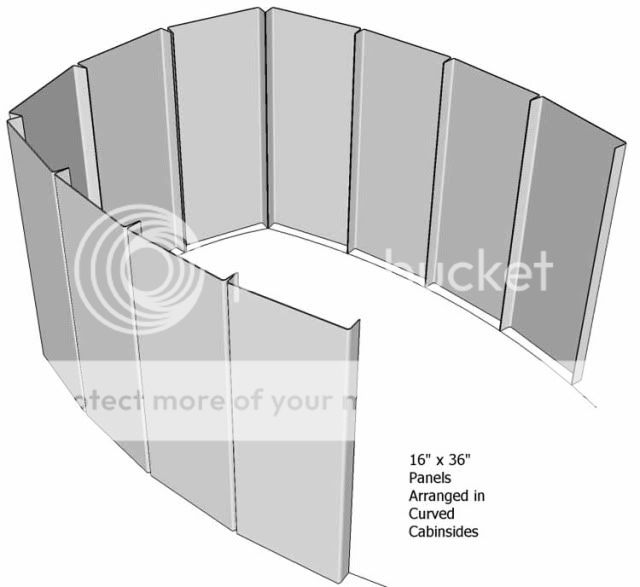
Some of the sketches here are design suggestions that may help inspire your ideas as you work inside the design or planning box?

Here is the top view of a pair of panels or "pans" as I've called them to give the idea of a shallow sided, wide, flat, thin material, formed piece of metal. The width is not important, you could divide the longest run of your cabin design by three or four or five, and discover the best or most attractive set of lines for the panel intersections.
I'd call attention to the corners show with the 1/2 radius because this can become an issue depending on your forming work supplier. The various alloys 5052, 5083, 5086 come in various H-numbers that describe their post smelting properties and some of these, H-321 for example in '83, have shown they require very wide radius to avoid stress cracks. But on the other hand, 5052 in H-32 can be bent with a much tighter radius or nose bar (some use a steel knife-edge nose bar) and still not strain crack.
A word of caution (from someone who's bought plenty of damaged material over the years ) to anyone not used to this fact of aluminum life: pay attention to this detail- closely. Do make sure you know what the results of bending the material you have, in the direction you plan to use your sheet goods, with the die or nose bar your service plans to offer you!!! (No sniveling! if you 'trust' the shop and all your work comes back cracked out and useless.)
(NOTE: the pan sides' bends do not have to be 90 deg's as shown. They could be less and therefore have a better single edge weld seam while not including a metal to metal space to conduct crevice corrosion sites.)
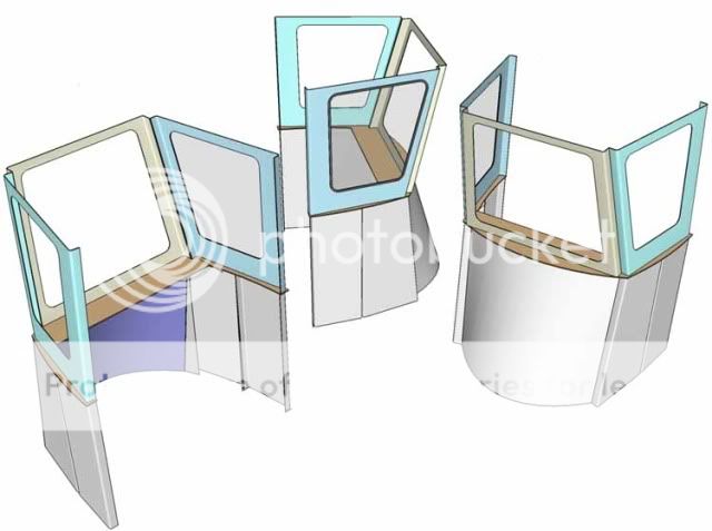
These following images are just offered to show the flexibility of this method of design then construction of the cabin. All that is being shown is examples of the lower shape of the cabin, its foot print on the deck as suggestions of how this could be modified for your preferences.


Here a provision for the basic structure of the helm area or dash is included in the transition plate or median band at the top of the lowers and bottom of the window band.
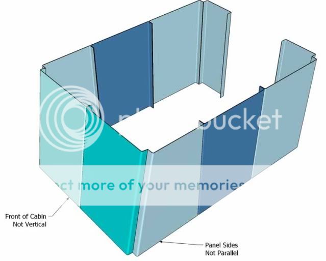
Here the pans are sloped along the forward bulkhead so the two forward most side panels are bent to accommodate this angle.

This combination of the previous ideas uses a rolled or cold formed forward dodger to give a less angular and more rounded shape to the forward lower part of the cabin.
This set of pans or bent panels becomes very stiff when welded to the deck of an aluminum boat. But it is much more work to build inside the skiff crawling around on your knees. So the next post will show a method to assemble this cabin off the boat, at working heights where easier work conditions can mean better fits and more uniform proportional welding.
Cheers,
Kevin Morin
Kenai, AK
Here is the top view of a pair of panels or "pans" as I've called them to give the idea of a shallow sided, wide, flat, thin material, formed piece of metal. The width is not important, you could divide the longest run of your cabin design by three or four or five, and discover the best or most attractive set of lines for the panel intersections.
I'd call attention to the corners show with the 1/2 radius because this can become an issue depending on your forming work supplier. The various alloys 5052, 5083, 5086 come in various H-numbers that describe their post smelting properties and some of these, H-321 for example in '83, have shown they require very wide radius to avoid stress cracks. But on the other hand, 5052 in H-32 can be bent with a much tighter radius or nose bar (some use a steel knife-edge nose bar) and still not strain crack.
A word of caution (from someone who's bought plenty of damaged material over the years ) to anyone not used to this fact of aluminum life: pay attention to this detail- closely. Do make sure you know what the results of bending the material you have, in the direction you plan to use your sheet goods, with the die or nose bar your service plans to offer you!!! (No sniveling! if you 'trust' the shop and all your work comes back cracked out and useless.)
(NOTE: the pan sides' bends do not have to be 90 deg's as shown. They could be less and therefore have a better single edge weld seam while not including a metal to metal space to conduct crevice corrosion sites.)
These following images are just offered to show the flexibility of this method of design then construction of the cabin. All that is being shown is examples of the lower shape of the cabin, its foot print on the deck as suggestions of how this could be modified for your preferences.
Here a provision for the basic structure of the helm area or dash is included in the transition plate or median band at the top of the lowers and bottom of the window band.
Here the pans are sloped along the forward bulkhead so the two forward most side panels are bent to accommodate this angle.
This combination of the previous ideas uses a rolled or cold formed forward dodger to give a less angular and more rounded shape to the forward lower part of the cabin.
This set of pans or bent panels becomes very stiff when welded to the deck of an aluminum boat. But it is much more work to build inside the skiff crawling around on your knees. So the next post will show a method to assemble this cabin off the boat, at working heights where easier work conditions can mean better fits and more uniform proportional welding.
Cheers,
Kevin Morin
Kenai, AK
kmorin
-
kmorin
- Donator 08, 09, 10, 11, 12, 13, 14, 15, 16, 17, 18, 19, 20, 21, 22, 23, 24
- Posts: 1743
- Joined: Mon Aug 18, 2008 1:37 am
- 15
- Location: Kenai, Alaska
Pilot House; Design-Build
I know that many owners who'd consider doing their own cabins will have their own way of dealing with the work flow of fabrication. I'm showing one method I've used for decades because it has helped make cabin building faster with less crawling on the knees, something in which I may put too much importance? To keep off my knees I'll do a lot, I've shown the Davis Jig complete hull rotisserie, I think, but the importance to me- may not be there for your younger stronger and more flexible knees! (then) Ignore this but it can help with accuracy of the build.
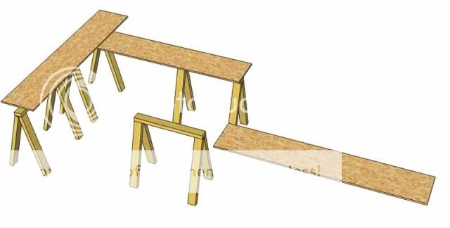
On top of saw horses I put down a working surface, flat and fairly stiff- by butt jointing with ply under the joints, a particle board or plywood working surface to layout the bottom of the cabin.
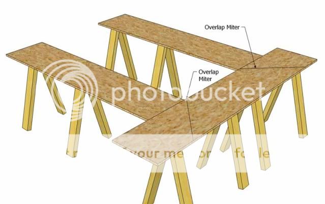
lapping the pieces needed to support the shape, I lap and miter the corners but T butts would work as well.
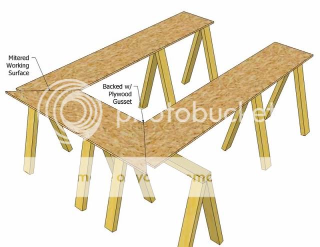
My goal is to get a flat surface that is stable and so I back the joints with ply and use dry wall screws to put on doubles or fish plates underneath.
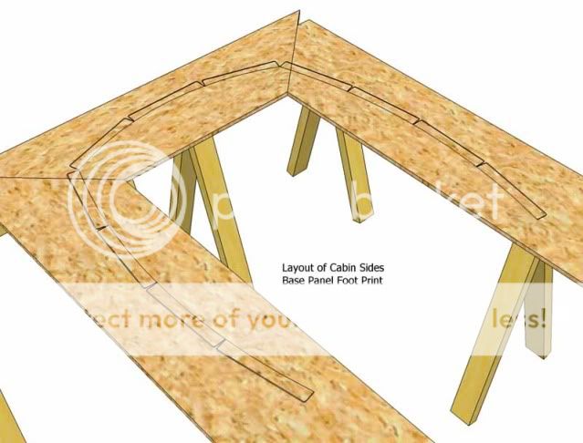
Then I draw the actual pans' lower edges as they will stand on the tack up jig, notice all this work is done at waist level- that's appealing for old backs supported by shaky knees. The pans themselves can be used to trace the outlines and the inner perimeter can be drawn by using a centerline board or aluminum straight edge then key offsets from centerline can be taken from the dimensions of the plans. The key dimensions would come from your plans developed in plan view.

The key to making this wood and metal layout and tacking jig work is the 'tab' or 'tack strips'. I refer to these small 1" x 1" x 1/8" squares of aluminum with a couple of dry wall screw sized holes- tabs/tack strips for want of better terms? These tack strips are screwed to the working layout surface at points that will restrict the shape of the pans to be tacked on.

Again, working at bench to ht.; the pans are aligned and tacked to the wooden work surface to begin the build.
Once tacked to the base, the inner edges can be tacked to the adjoining edges and the result is a stiff shape what will retain it form while the transition plate or dash board panel is added (tacked).
The cabin can be left on this jig or removed if a few tie bars are laid along the lower edges to hold shape in both directions until the cabin can be tacked to the deck.
Next we'll go back to some design ideas and discuss one of the least appreciated pieces of the cabin- the brow. But to get there, we'll look first at the cabin top panel and various methods of designing forming and assembling that element of the house.
Cheers,
Kevin Morin
Kenai, AK
On top of saw horses I put down a working surface, flat and fairly stiff- by butt jointing with ply under the joints, a particle board or plywood working surface to layout the bottom of the cabin.
lapping the pieces needed to support the shape, I lap and miter the corners but T butts would work as well.
My goal is to get a flat surface that is stable and so I back the joints with ply and use dry wall screws to put on doubles or fish plates underneath.
Then I draw the actual pans' lower edges as they will stand on the tack up jig, notice all this work is done at waist level- that's appealing for old backs supported by shaky knees. The pans themselves can be used to trace the outlines and the inner perimeter can be drawn by using a centerline board or aluminum straight edge then key offsets from centerline can be taken from the dimensions of the plans. The key dimensions would come from your plans developed in plan view.
The key to making this wood and metal layout and tacking jig work is the 'tab' or 'tack strips'. I refer to these small 1" x 1" x 1/8" squares of aluminum with a couple of dry wall screw sized holes- tabs/tack strips for want of better terms? These tack strips are screwed to the working layout surface at points that will restrict the shape of the pans to be tacked on.
Again, working at bench to ht.; the pans are aligned and tacked to the wooden work surface to begin the build.
Once tacked to the base, the inner edges can be tacked to the adjoining edges and the result is a stiff shape what will retain it form while the transition plate or dash board panel is added (tacked).
The cabin can be left on this jig or removed if a few tie bars are laid along the lower edges to hold shape in both directions until the cabin can be tacked to the deck.
Next we'll go back to some design ideas and discuss one of the least appreciated pieces of the cabin- the brow. But to get there, we'll look first at the cabin top panel and various methods of designing forming and assembling that element of the house.
Cheers,
Kevin Morin
Kenai, AK
kmorin
-
kmorin
- Donator 08, 09, 10, 11, 12, 13, 14, 15, 16, 17, 18, 19, 20, 21, 22, 23, 24
- Posts: 1743
- Joined: Mon Aug 18, 2008 1:37 am
- 15
- Location: Kenai, Alaska
Pilot House; Design-Build
To design the brow we'd have to have a top of some kind to mount the brow because as I hope the sketches show... the brow is a surface mounted to the forward edge of the cabin top. To put on the top we'll need to hold it in shape and do some fitting before we can install a top. First we need to address the shape of the top so we'll discuss camber frame layout.
The top of most cabins have camber or curvature; upward in this case. A cambered surface or a 'camber' is part of a cylinder, but as I've heard and used the term the amount of curve is usually very slight or shallow. This means the radius of the camber's cylinder is big and the center may be fifty feet from the cambered deck? Not very easy to layout a camber if the compass needs to be 25 or 50' long.
The technique to layout shallow curves, as I understand and practice, is to 'expand a circle'. We'll look at that in a minute, but first; Note that this work might be done in CAD and the layout method I'm going to show would not be necessary. Further if you're doing the design and cutting in CAD controlled systems then this layout is not needed but it is provided for those who're working with older generation of tools to form the camber patterns or frames.
This example series was done to discuss cambered deck beams not cabin tops camber frames- but the exact methods apply when expanding a circle.

The blue half circle is the radius of the depth of the camber. Across a small cabin, a 6" curved top may look a little to exaggerated but this was done for a 16' or 17' beam deck. So in a 6' cabin width- a 2" or 3" camber depth of the arc upward might look more conservative?
The orientation references are there to make sure everyone see's where we're planning to use this curve we're getting ready to draw.
There are a couple of important notes here; first that the distance from the center of the circle to the maximum width of the cabin is used; and next the blue circle's outer circumference or 1/4 arc of the circle is divided into four equal lengths. These arcs are equal, this has to be done by walking dividers up and down that arc until the arc subsections are equal- three divisions will work fine for most 6-8' cabin camber frames. The radius below the arc is not divided equally.

There is a lot of info here that may not become clear until the next few sketches but in words: #1 each of the ARC segments are drawn as vertical lines to the circle's horizontal radius line. #2 this line is the length of the vertical distance at each of the four divisions of the 1/2 frame distance. #3 the center of the arc/camber will the full depth of the radius, vertical to the baseline. #4 the vertical distance above the baseline of the 1/4 span will be the inner most arc segment's vertical length off the baseline.

Here is the expansion of the circle. The vertical lengths of each arc segment's end point above the baseline marked off at the equal divisions of the baseline, which is this case is 1/2 the maximum width of the top of the window band of the cabin being designed. If the cabin tapers there will other layout steps to trim those camber frames, at this time work on the (1/2 of) maximum beam only.

So this set of points can be battened out on wood or metal material to draw a cambered (top) frame that has a fixed depth of curvature for a given span of width.

Here is an image of what I mean by 'battening' the points, drawing a clean and fair curve though the five (four per side plus center) points to allow a line to be struck for cutting and sanding to form a clean camber frame in metal of a wooden former.
Here, a purple colored aluminum angle is used to bend to the points but will flex only, not kink or permanently bend so it qualifies as a batten or drawing tool. The cross section size of aluminum extrusions has to be selected to meet the curves they can draw.
How does this fit into the cabin top?
to put the top on, hold its shape while adding some permanent aluminum frames these pieces of temporary wooden formers need to be layout and cut to the camber of the cabin top. This method could be used to layout and cut metal frames for wider spans or 'walk on top' cabins where the top becomes a deck or has to hold crew. But we're not addressing that in this thread, we're just trying to show methods to shape and form a cabin to keep off weather so this cabin top framing could be left without interior framing.
Cheers,
Kevin Morin
Kenai, AK
The top of most cabins have camber or curvature; upward in this case. A cambered surface or a 'camber' is part of a cylinder, but as I've heard and used the term the amount of curve is usually very slight or shallow. This means the radius of the camber's cylinder is big and the center may be fifty feet from the cambered deck? Not very easy to layout a camber if the compass needs to be 25 or 50' long.
The technique to layout shallow curves, as I understand and practice, is to 'expand a circle'. We'll look at that in a minute, but first; Note that this work might be done in CAD and the layout method I'm going to show would not be necessary. Further if you're doing the design and cutting in CAD controlled systems then this layout is not needed but it is provided for those who're working with older generation of tools to form the camber patterns or frames.
This example series was done to discuss cambered deck beams not cabin tops camber frames- but the exact methods apply when expanding a circle.
The blue half circle is the radius of the depth of the camber. Across a small cabin, a 6" curved top may look a little to exaggerated but this was done for a 16' or 17' beam deck. So in a 6' cabin width- a 2" or 3" camber depth of the arc upward might look more conservative?
The orientation references are there to make sure everyone see's where we're planning to use this curve we're getting ready to draw.
There are a couple of important notes here; first that the distance from the center of the circle to the maximum width of the cabin is used; and next the blue circle's outer circumference or 1/4 arc of the circle is divided into four equal lengths. These arcs are equal, this has to be done by walking dividers up and down that arc until the arc subsections are equal- three divisions will work fine for most 6-8' cabin camber frames. The radius below the arc is not divided equally.
There is a lot of info here that may not become clear until the next few sketches but in words: #1 each of the ARC segments are drawn as vertical lines to the circle's horizontal radius line. #2 this line is the length of the vertical distance at each of the four divisions of the 1/2 frame distance. #3 the center of the arc/camber will the full depth of the radius, vertical to the baseline. #4 the vertical distance above the baseline of the 1/4 span will be the inner most arc segment's vertical length off the baseline.
Here is the expansion of the circle. The vertical lengths of each arc segment's end point above the baseline marked off at the equal divisions of the baseline, which is this case is 1/2 the maximum width of the top of the window band of the cabin being designed. If the cabin tapers there will other layout steps to trim those camber frames, at this time work on the (1/2 of) maximum beam only.
So this set of points can be battened out on wood or metal material to draw a cambered (top) frame that has a fixed depth of curvature for a given span of width.
Here is an image of what I mean by 'battening' the points, drawing a clean and fair curve though the five (four per side plus center) points to allow a line to be struck for cutting and sanding to form a clean camber frame in metal of a wooden former.
Here, a purple colored aluminum angle is used to bend to the points but will flex only, not kink or permanently bend so it qualifies as a batten or drawing tool. The cross section size of aluminum extrusions has to be selected to meet the curves they can draw.
How does this fit into the cabin top?
to put the top on, hold its shape while adding some permanent aluminum frames these pieces of temporary wooden formers need to be layout and cut to the camber of the cabin top. This method could be used to layout and cut metal frames for wider spans or 'walk on top' cabins where the top becomes a deck or has to hold crew. But we're not addressing that in this thread, we're just trying to show methods to shape and form a cabin to keep off weather so this cabin top framing could be left without interior framing.
Cheers,
Kevin Morin
Kenai, AK
kmorin
Re: Pilot House; Design-Build
Agricultural maybe, but I love the work boat look and design.
-
kmorin
- Donator 08, 09, 10, 11, 12, 13, 14, 15, 16, 17, 18, 19, 20, 21, 22, 23, 24
- Posts: 1743
- Joined: Mon Aug 18, 2008 1:37 am
- 15
- Location: Kenai, Alaska
Re: Pilot House; Design-Build
Reelsong, we'll all had to sort of get used to the work boat look but do you notice you and I referring to the 'work boat' look? I'd like to find that sweet spot like the cabs on sedans, even trawlers or types where the stand up helm is- 'Suhhhh-WEET!" (term introduced by one of my crew of builders all 1/2 to 1/3 as ancient as their welder) to look at- along with the (gunboat sleek) hull lines of your new Cope-song.
Well back to work, or at least back to discussing the how to part of ONE method of doing this work.
First to digress a bit, windscreens can rake (lean) aft, be plumb (vertical) or rake forward, and almost all of mine will be shown forward. Here's what I've seen and think is the reason, and I prefer to see the glass panels lean aft fro sleek looks. If a green one ever comes aboard over the bow it would be curling downward as it traveled aft. So if the glass panels raked forward they'd be more or less parallel to the impact instead of leaned aft where the impacting water would be more at 90degs to that panel. Plumb windscreens are in between the two but considered in this rationalization as more toward the 'take it on the chin' kind of design than 'go with the flow' forward raking windscreen.
Next cabin space is more or less premium boat space and giving up floor because the glass rakes aft, well it drives lots of skiff owners and builders to adopt the forward rake so they can get closer to the glass, put their electronics overhead in the area above the glass, and make the helm more compact fore and aft.
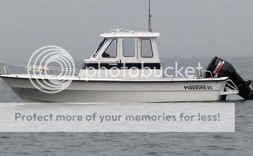
here's an aft raked glass cabin of about the class we're discussing, I'm sure you've seen more of the type? I think the cabin floor/deck/sole area lost by standing aft away from the glass rake may be a poor cost choice given the effort and materials to build any cabin. I always want to maximize the deck/sole/floor but then 'it in the eyes of the skipper' that beautiful designs are decided.

Here is a plastic composite cabin and it may be sitting on a fuel cell? not sure on that, but the lines mean that the crew is aft the windscreen by a few feet more than is absolutely needed so I'm repeating the 'get close to the glass' idea that is allowed by the forward raking screen.
OK... back to the progress of designing and building your own cabin.
Here's the temporary wood formers cut to a camber, tabs screwed to their trimmed to fit inside ends and then tacked inside the window band panels. The forward panels' top camber is done by projection; lay a straight edge along the two fomers' top edges and mark the curve for and aft (add a bar or angle above the opening aft) and then these pieces can be cut in place (jig saw) or taken down and cut (band saw and belt sander) and retacked while the two wood camber frames hold the sides' locations.
Now....
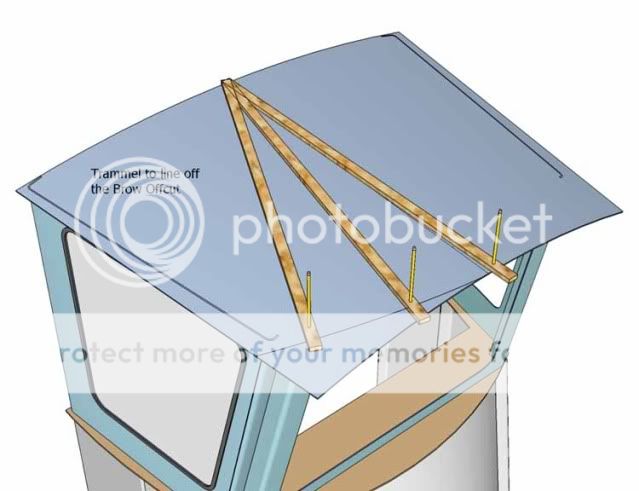
Drape the top panel blank, shown here already somewhat fit to along the sides. Mark the overhangs if there will be one, mark a brow radius if there will be one, and mark the aft overhang to your plans from the 'design box' in the first few posts.
A trammel bar, radius bar, wood compass bar- whatever term you call this piece of wood or metal with a couple holes is shown located at the after edge of the top and then striking off a curve along the forward edge of the overhanging cabin top. The distance of overhang is up to you, some like them wider or farther fore and aft, others tighter to the windscreen. If the radius of this top edge's forward curve is not centered on the cabin top as I show here.... then you'll have to put a bar or plate aft the cabin top's aft edge and set up some way to run the trammel bar from there! The farther away, clearly the wider and slower arc you will describe along the forward edge of the cabin top as you define the brow's aft and upper intersection line.
long slow arc center is likely aft the long full cabin?

shorter radius curved brow, center is probably on the cabin top, maybe even forward of the aft most edge?
Using the temporary formers top curves (cambers) you can strike the forward glass panel and after hatch or companion way top bar to the same curves. Then after cutting those curves, (they may not be the same as the camber frames if the windscreen has two or more panels so please note that fact in this set of images) the top panel can be pulled down to rough fit the shape and the brow's curve cut to a curve that is short radius or long depending on the lines of the cabin that most appeal to your eye.
Cheers,
Kevin Morin
Kenai, AK
Well back to work, or at least back to discussing the how to part of ONE method of doing this work.
First to digress a bit, windscreens can rake (lean) aft, be plumb (vertical) or rake forward, and almost all of mine will be shown forward. Here's what I've seen and think is the reason, and I prefer to see the glass panels lean aft fro sleek looks. If a green one ever comes aboard over the bow it would be curling downward as it traveled aft. So if the glass panels raked forward they'd be more or less parallel to the impact instead of leaned aft where the impacting water would be more at 90degs to that panel. Plumb windscreens are in between the two but considered in this rationalization as more toward the 'take it on the chin' kind of design than 'go with the flow' forward raking windscreen.
Next cabin space is more or less premium boat space and giving up floor because the glass rakes aft, well it drives lots of skiff owners and builders to adopt the forward rake so they can get closer to the glass, put their electronics overhead in the area above the glass, and make the helm more compact fore and aft.
here's an aft raked glass cabin of about the class we're discussing, I'm sure you've seen more of the type? I think the cabin floor/deck/sole area lost by standing aft away from the glass rake may be a poor cost choice given the effort and materials to build any cabin. I always want to maximize the deck/sole/floor but then 'it in the eyes of the skipper' that beautiful designs are decided.
Here is a plastic composite cabin and it may be sitting on a fuel cell? not sure on that, but the lines mean that the crew is aft the windscreen by a few feet more than is absolutely needed so I'm repeating the 'get close to the glass' idea that is allowed by the forward raking screen.
OK... back to the progress of designing and building your own cabin.
Here's the temporary wood formers cut to a camber, tabs screwed to their trimmed to fit inside ends and then tacked inside the window band panels. The forward panels' top camber is done by projection; lay a straight edge along the two fomers' top edges and mark the curve for and aft (add a bar or angle above the opening aft) and then these pieces can be cut in place (jig saw) or taken down and cut (band saw and belt sander) and retacked while the two wood camber frames hold the sides' locations.
Now....
Drape the top panel blank, shown here already somewhat fit to along the sides. Mark the overhangs if there will be one, mark a brow radius if there will be one, and mark the aft overhang to your plans from the 'design box' in the first few posts.
A trammel bar, radius bar, wood compass bar- whatever term you call this piece of wood or metal with a couple holes is shown located at the after edge of the top and then striking off a curve along the forward edge of the overhanging cabin top. The distance of overhang is up to you, some like them wider or farther fore and aft, others tighter to the windscreen. If the radius of this top edge's forward curve is not centered on the cabin top as I show here.... then you'll have to put a bar or plate aft the cabin top's aft edge and set up some way to run the trammel bar from there! The farther away, clearly the wider and slower arc you will describe along the forward edge of the cabin top as you define the brow's aft and upper intersection line.
long slow arc center is likely aft the long full cabin?
shorter radius curved brow, center is probably on the cabin top, maybe even forward of the aft most edge?
Using the temporary formers top curves (cambers) you can strike the forward glass panel and after hatch or companion way top bar to the same curves. Then after cutting those curves, (they may not be the same as the camber frames if the windscreen has two or more panels so please note that fact in this set of images) the top panel can be pulled down to rough fit the shape and the brow's curve cut to a curve that is short radius or long depending on the lines of the cabin that most appeal to your eye.
Cheers,
Kevin Morin
Kenai, AK
Last edited by kmorin on Wed Mar 18, 2015 4:16 pm, edited 1 time in total.
kmorin
-
kmorin
- Donator 08, 09, 10, 11, 12, 13, 14, 15, 16, 17, 18, 19, 20, 21, 22, 23, 24
- Posts: 1743
- Joined: Mon Aug 18, 2008 1:37 am
- 15
- Location: Kenai, Alaska
Re: Pilot House; Design-Build
Time for a little clean up the thread post.
I didn't show the projection of the top of the camber frames onto the forward windscreen panels' top or the after bulkhead's top plate across the opening or companionway/doorway because I thought that worked well in words? In case that has not been clear the main note of this work is the straight edge MUST be kept parallel to the keel plane for this to work well! If you angle the flat bar used to mark the arc of the camber forward - or aft, the shape will be slightly parabolic not cylindrical, and the curves while similar are not identical in projection.
The BROW.. this is big design deal and so I'll take extra time with this small curved piece of metal. The brow can influence how the entire cabin looks. Take time to go surfing for cabins' images and then pay close attention to how influential this little "ball cap bill" piece of metal is in the 'looks' of a boat cabin!

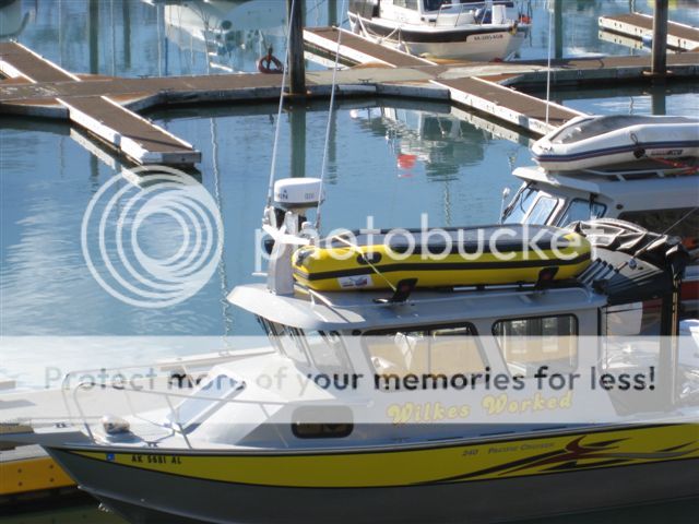
Pronounced brow but tucked in close to the window band, taller brow above the cabin top plane's curve but still creating the 'look' of this cabin.
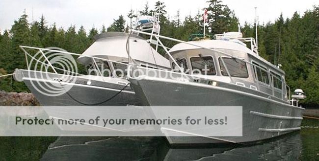
here are what look like matching hulls with different brow lines and sizes, one a fly bridge (huge brow shape) the other is a large brow but scaled down do you notice the difference in the overall look of the two boat?

How about NO BROW? this may not be a metal boat but the cabin top line doesn't even have a brow over the windscreen- sure changes the look of this boat's profile.
an extremely clean lined, well built boat with no brow on the cabin's upper line.
To me, this added brow at the cabin top just makes the entire boat look better, not that is was homely in my eyes without the brow... but now! Wow what a pretty boat! The brow seems to echo and reflect the lines of the hull?
We'll look at some other examples then spend a little time on the geometry of this major contributor to cabin's style and looks.
cheers,
Kevin Morn
Kenai, AK
I didn't show the projection of the top of the camber frames onto the forward windscreen panels' top or the after bulkhead's top plate across the opening or companionway/doorway because I thought that worked well in words? In case that has not been clear the main note of this work is the straight edge MUST be kept parallel to the keel plane for this to work well! If you angle the flat bar used to mark the arc of the camber forward - or aft, the shape will be slightly parabolic not cylindrical, and the curves while similar are not identical in projection.
The BROW.. this is big design deal and so I'll take extra time with this small curved piece of metal. The brow can influence how the entire cabin looks. Take time to go surfing for cabins' images and then pay close attention to how influential this little "ball cap bill" piece of metal is in the 'looks' of a boat cabin!
Pronounced brow but tucked in close to the window band, taller brow above the cabin top plane's curve but still creating the 'look' of this cabin.
here are what look like matching hulls with different brow lines and sizes, one a fly bridge (huge brow shape) the other is a large brow but scaled down do you notice the difference in the overall look of the two boat?
How about NO BROW? this may not be a metal boat but the cabin top line doesn't even have a brow over the windscreen- sure changes the look of this boat's profile.
an extremely clean lined, well built boat with no brow on the cabin's upper line.
To me, this added brow at the cabin top just makes the entire boat look better, not that is was homely in my eyes without the brow... but now! Wow what a pretty boat! The brow seems to echo and reflect the lines of the hull?
We'll look at some other examples then spend a little time on the geometry of this major contributor to cabin's style and looks.
cheers,
Kevin Morn
Kenai, AK
kmorin
Re: Pilot House; Design-Build
Hello Kevin. Thank you for placing this guidance and assistance. The entire subject of pilot house design and execution is likely one of the more difficult phases of a build or mod. As you know, my project ran into a sticking point right here as I fabricated a house onto an existing boat. I will get a few pictures up today that show where I am at now. I very much appreciate your willingness to lend your trade craft and design advice. Now that I have seen some examples, I have not missed it as far as I feared. I should really wait for an experienced eye to determine that before Instart with the high fives..more to come later today. My construction technique is crude in that it is post and beam ( moment frame) with what will be shear panel in-fill's
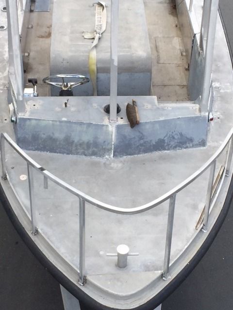
To locate the windows.
One big question that I have is regarding weight distribution and roll axis. I have been really concerned about the rolling moment and how that is influenced by the design of the hull and the whole mass/ acceleration issue. I can crank out the math, but I have no basis for the reactions. I am a total numb nuts out in deep left on the practical effects or anything beyond a ridiculously wide WAG.
Again. Thank you.
-
kmorin
- Donator 08, 09, 10, 11, 12, 13, 14, 15, 16, 17, 18, 19, 20, 21, 22, 23, 24
- Posts: 1743
- Joined: Mon Aug 18, 2008 1:37 am
- 15
- Location: Kenai, Alaska
Welcome to the AAB
astglenn, welcome to the forum, plenty to read here about aluminum boats in all aspects, from design to building and fishing.
I'm not sure which marine hull variable you're working to solve, but there is a dual effect to cabin wt high off the waterline. One is to dampen roll, not an intuitive conclusion but true. The other is to reduce the angle of heel at which the skiff will actually go over but that is such a catastrophic angle that I don't think its important to look at that aspect of cabin wt? (my take, some may consider all boat 'open ocean' therefore argue this is important?)
If you could show the beam of the boat at the waterline, some idea of the section shape of the hull's master station, and give some idea of the size (LOA) and what her construction is; typically? I'm pretty sure we could rough out the relative stability with the cabin and without? I may be reading your remarks incorrectly but it seems you're asking if adding a stand up helm enclosure (structure) will the boat become less or even- unstable?
Obviously a cabin of this type on a canoe hull would make that beam to length ratio hull, with its extremely low CG (2" off the bottom until loaded) pretty unstable. But most skiffs with a 5' chine could stand a cabin of this type without becoming unstable. An intermediate type of hull would be the 4' bottom round chine, Lund, Gregor, Starcraft hulls that would probably be the too narrow to take this type cabin as well?
Glenn, let's see some pics and we'll all tell you what we think you should or could do.
Cheers,
Kevin Morin
Kenai, AK
kmorin
Re: Pilot House; Design-Build
Great thread and subject as usual , thanks again Kevin
Welcome to AAB astglenn there is an incredible wealth of info here not to mention a great bunch of guys
Welcome to AAB astglenn there is an incredible wealth of info here not to mention a great bunch of guys
Re: Pilot House; Design-Build
Thank you for the hospitality. I fully agree that this forum is inhabited by encouragement, talent and a general will of the membership to help others where they can. Guys like Kevin are what seems to be missing from society these days. A person that possesses creative intelligence, a willingness and means of transferring some of it to others, and a profound ability to express it all through his own direct craftsmanship. That is in a nutshell, what we need a lot more of.ReelSong wrote:Great thread and subject as usual , thanks again Kevin
Welcome to AAB astglenn there is an incredible wealth of info here not to mention a great bunch of guys
Now to figure out how to get some photographs of my project today that somehow make my decisions and craftsmanship look a lot better than reality. You see, this is my big problem. Trying to get my reality and expectation somewhere within sight of each other. Aint it always?
Re: Pilot House; Design-Build
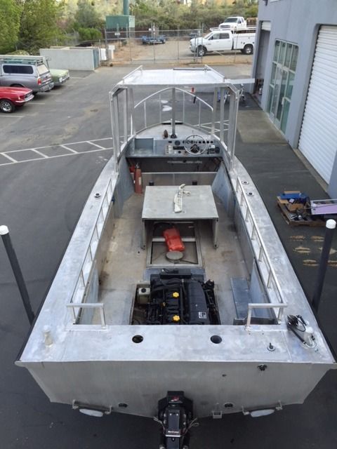
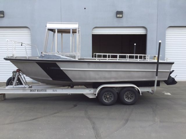
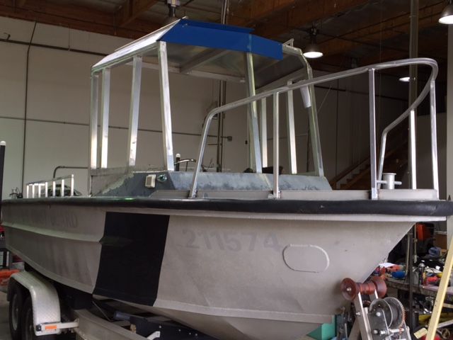
Here are some basic views of the boat and where I am at now. I found this very cool boat in the Federal Defense junk pile and went and hauled it out of USCG Station- Corpus Cristy TX, all the way back here to CA. I wanted this boat pretty bad. This was started in 08. I had an out of the blue heart attack that ended up with the boat laying in the yard until about Jan of this year. I have a bunch more capabilities now to get her completed, including a 251 Miller and spool gun. My plan was to initially use canvas and isenglass for the entire frame cover except for the roof. I now really want to infill the posts with 3/16" sheet which would be cut out to take windows that are 80% +/- of the openings, then install 1/4" laminated glass via a rubber glazing extrusion "weatherstrip." The offset in the posts is going to force an issue of laying the infill panels and windows queer to the post lines. Not sure that it is not a better idea to start over with a design in hand. I have screwed this up. I am quite willing to start over. SOS!! Kevin?


-
kmorin
- Donator 08, 09, 10, 11, 12, 13, 14, 15, 16, 17, 18, 19, 20, 21, 22, 23, 24
- Posts: 1743
- Joined: Mon Aug 18, 2008 1:37 am
- 15
- Location: Kenai, Alaska
Re: Pilot House; Design-Build
astglenn, I'm sorry to hear your pump cavitated on you, but glad to be typing to you as you enjoy your continued span "under the sun", and thanks for the very kind words. Welder, our host and generous bandwidth renter on all our behalf, has put up the site to focus on welded aluminum and he's been the most consistent advocate of these boats online for quite a few years.
In keeping with his ideals, example and leadership; those of us with similar interests hang out here instead of the more generic marine sites where even plastic and dead trees are foolishly used to make boats! Not here, AAB.com provides space to get to the heart of the Miracle Metal's uses for boats and that's what most of us try to do?
I'm the resident mill scale gnat-zee where I snivel regularly to have mill scale removed, so that corrosion can be minimized but I also try to post illustrated series that show ONE WAY, not the only way, (and I don't argue that idea) but one way for people to do their own work. Most people find that after they've done it my way, they find a better and more efficient way of their own- in the meantime there's at least some step by step method of getting results as they're learning.
After seeing the boat, understanding the hull's shape by some common experience I guess I'd ask you to give us an SOR. Statement of Requirements, (design narrative in some circles) simply states what the goals or 'must haves' are for the boat.
Does the foredeck in this boat have to remain flat, fixed, low and cramped OR can the foredeck be raised? The class of boat may change if the foredeck is raised into a trunk cabin but that may be out of scope?
Does the sheer have to remain flat? Could a raised foredeck add to the forward cabin volume and change the basis for the cabin structure?
These fundamental questions are to explore your limits of the work. I do know that in an online post suggestions spend your money freely, the bigger the scope the more you spend but those are limits you're free to reign in!

Why did I ask? here is a 25' dayboat that has a similarly shallow V and low bow structure but the raised trunk allows a bit of volume forward, and then a reasonably low profile cabin because the trunk (tan colored with hand rail defining the top and outboard port side) shape somewhat transitions the bow to the windscreen.
If your hull had a deck shelf left but was cut out to allow a trunk and that reached aft a bunks' length ?? The windscreen might be located farther aft, helping the lines of the boat in profile to be more balanced and giving more useful cabin? The lines of the cabin windscreen may still be raked aft, plumb or raked forward, my foundational question is; can the existing deck be modified to consider a trunk and windscreen type of cabin.
Let me know if I'm busting the boat budget, blank page isn't necessary a blank check, and we'll try to follow your ideas. My first impression is that the entire sheer can be modified (upward in the forward 1/2) and the skiff's profile will change. Next that increase forward could become a useful cabin space AND that could be the basis for a cabin that is more integrated with the boat? This would change the entire character of the boat and for general use make is more comfortable that the current tacked up windscreen/dodger.
Next, to materials. There are two separate sets or rectangular metal tubing products. One is architectural and has sharp corners and the second is rounded or ASTM standards. The only thing to make sure you're aware about the two shapes' properties is the alloys. If the alloys are 6061 in both cases? That means welding and performance are predictable but ... if the alloy is not 6061 then its worth considering some break bend testing to insure you don't do work that embrittles an unknown or unconfirmed alloy. Why do the work twice? once ill informed and the second time saying sailor like slurs about the mothers of the fellow that didn't label the 'wrong' alloy!
I avoid the sharp corners if possible in boats and try to use the rounded rectangular shapes to the extent that if I'm forced into square corner materials I will usually use a router with carbide bit to 'round over' or bullnose the corners. Lots of work but I prefer the non-sharp edges in case someone bangs into one in a lumpy ride!
Square stock cabin posts in this application are more work than buying sheet and making the window band (at least) from new metal. The amount of welding increases pretty radically using a post then fillers of flat panels to hold the rubber glass mounting extrusions.
Uprights in hand rails or bow pulpits will look more attractive if they're raked forward, (or some aft) and the rake may be varied; but in general, boats avoid plumb lines as they're less complimentary with the curves we see in a seaway. I'm not saying there's that much functional value to replacing the hand railing, or bow railing, but all these items can contribute to the look of boat, so they're up for discussion until you finalize your decisions.
Now we've seen the boat, let us know some ideas for the scope of the design you're willing to entertain and we'll put up some sketches of ideas that will allow you to explore what could be done with this hull.
Reelsong, thanks for the kind words, its always a pleasure to have accolades from other builders.
Cheers,
Kevin Morin
In keeping with his ideals, example and leadership; those of us with similar interests hang out here instead of the more generic marine sites where even plastic and dead trees are foolishly used to make boats! Not here, AAB.com provides space to get to the heart of the Miracle Metal's uses for boats and that's what most of us try to do?
I'm the resident mill scale gnat-zee where I snivel regularly to have mill scale removed, so that corrosion can be minimized but I also try to post illustrated series that show ONE WAY, not the only way, (and I don't argue that idea) but one way for people to do their own work. Most people find that after they've done it my way, they find a better and more efficient way of their own- in the meantime there's at least some step by step method of getting results as they're learning.
After seeing the boat, understanding the hull's shape by some common experience I guess I'd ask you to give us an SOR. Statement of Requirements, (design narrative in some circles) simply states what the goals or 'must haves' are for the boat.
Does the foredeck in this boat have to remain flat, fixed, low and cramped OR can the foredeck be raised? The class of boat may change if the foredeck is raised into a trunk cabin but that may be out of scope?
Does the sheer have to remain flat? Could a raised foredeck add to the forward cabin volume and change the basis for the cabin structure?
These fundamental questions are to explore your limits of the work. I do know that in an online post suggestions spend your money freely, the bigger the scope the more you spend but those are limits you're free to reign in!
Why did I ask? here is a 25' dayboat that has a similarly shallow V and low bow structure but the raised trunk allows a bit of volume forward, and then a reasonably low profile cabin because the trunk (tan colored with hand rail defining the top and outboard port side) shape somewhat transitions the bow to the windscreen.
If your hull had a deck shelf left but was cut out to allow a trunk and that reached aft a bunks' length ?? The windscreen might be located farther aft, helping the lines of the boat in profile to be more balanced and giving more useful cabin? The lines of the cabin windscreen may still be raked aft, plumb or raked forward, my foundational question is; can the existing deck be modified to consider a trunk and windscreen type of cabin.
Let me know if I'm busting the boat budget, blank page isn't necessary a blank check, and we'll try to follow your ideas. My first impression is that the entire sheer can be modified (upward in the forward 1/2) and the skiff's profile will change. Next that increase forward could become a useful cabin space AND that could be the basis for a cabin that is more integrated with the boat? This would change the entire character of the boat and for general use make is more comfortable that the current tacked up windscreen/dodger.
Next, to materials. There are two separate sets or rectangular metal tubing products. One is architectural and has sharp corners and the second is rounded or ASTM standards. The only thing to make sure you're aware about the two shapes' properties is the alloys. If the alloys are 6061 in both cases? That means welding and performance are predictable but ... if the alloy is not 6061 then its worth considering some break bend testing to insure you don't do work that embrittles an unknown or unconfirmed alloy. Why do the work twice? once ill informed and the second time saying sailor like slurs about the mothers of the fellow that didn't label the 'wrong' alloy!
I avoid the sharp corners if possible in boats and try to use the rounded rectangular shapes to the extent that if I'm forced into square corner materials I will usually use a router with carbide bit to 'round over' or bullnose the corners. Lots of work but I prefer the non-sharp edges in case someone bangs into one in a lumpy ride!
Square stock cabin posts in this application are more work than buying sheet and making the window band (at least) from new metal. The amount of welding increases pretty radically using a post then fillers of flat panels to hold the rubber glass mounting extrusions.
Uprights in hand rails or bow pulpits will look more attractive if they're raked forward, (or some aft) and the rake may be varied; but in general, boats avoid plumb lines as they're less complimentary with the curves we see in a seaway. I'm not saying there's that much functional value to replacing the hand railing, or bow railing, but all these items can contribute to the look of boat, so they're up for discussion until you finalize your decisions.
Now we've seen the boat, let us know some ideas for the scope of the design you're willing to entertain and we'll put up some sketches of ideas that will allow you to explore what could be done with this hull.
Reelsong, thanks for the kind words, its always a pleasure to have accolades from other builders.
Cheers,
Kevin Morin
kmorin
-
goatram

- Donator 08, 09, 10, 11, 12, 13, 14, 15, 16, 17, 18, 19
- Posts: 1959
- Joined: Wed Apr 09, 2008 11:53 pm
- 16
- Location: Stanwood WA
Re: Pilot House; Design-Build
Glenn
Welcome to AAB
Your right to ask Kevin for some insight. I modified my Northriver; adding a cabin to the existing window frame. It worked but it was not pleasing to the eye. I could live with it but others saw the Ugly in my design. If I could redo I would cut off the original window and start new. Moving the helm back would also help to smooth out the lines and the ride. Kevin and paint software while help the design process. Enjoy
John Risser aka goatram
33' RBW with twin 250 Hondas (Aliens)
2015 Ford F350 Dually
Master of R&D aka Ripoff and Duplicate
33' RBW with twin 250 Hondas (Aliens)
2015 Ford F350 Dually
Master of R&D aka Ripoff and Duplicate
Re: Pilot House; Design-Build
Kevin. At this point, I am willing to let the scope creep upward to get it useful. Unless it gets crazy, I am ok with some costs. Boats of all kinds have been separating me from coin for a long time. Just following tradition!
She is 1985 Monarch. 200 hp VM turbo diesel and a Bravo 2X. 200 gallons fuel. 100 gallon belly tank and two 50 gallon saddles. I have a new 12" SIMRAD NSS Nav suite for her.
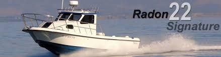
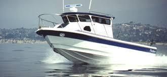
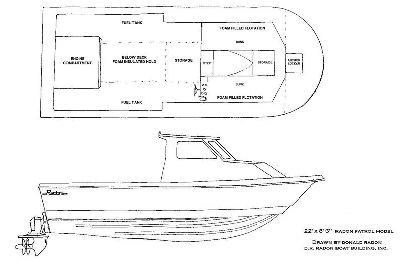
The SOR for this build is all about fishing. I fish the Southern California area. I also fish NorCal, but So Cal is where I really like to be. Typically, this boat will need to run 25 -40 miles off for the Tuna on the flat calm days when they are feeling friendly, and inshore for lobster, Halibut, etc. A head would be extremely helpful. I have 5 daughters I have looked at several ways to possibly make that happen (Portapoti hidden in seat etc) I had thought about a cabin build along the lines of a Radon 22. This has been milling around in my head, but my design skills are not up to the task. This type of enclosure would be a great design for what I do. I would say that the cabin would be about hiding a head in somehow more than anything else. The raised area in the front and the subsequent shorter walls sure makes a better looking enclosure. I had looked at lowering the floor in the helm area, but the hull gets pretty narrow. Being so far forward makes for a huge cockpit for a 22' boat. That part is great. The boat is really a life support and transportation system for the best 1 scoop live bait tank that I can place on the deck and three or four fisherman. Its really more like recreational espionage than fishing. We get a bit carried away with it.
Here are a couple of photographs of the 22' Radon in a couple of cabin configurations. The are located well forward of center and the hull seems to be at least on the same planet as my diesel powered war sled. I am not into fancy. I am into type 1-A heavy duty with the sharp edges rounded off, if that makes any sense. I would love to build an alloy version of a Radon or that "type" of design at some point in my life. The learning I do here will be indispensable.
Other than speaking to the Coxwain that ran this boat at the USCG station, I have no idea of her sea keeping abilities or handling characteristics. The dead rise measures 20 degrees at the stern and looks to remain sharp all the way forward. The Coxwain ran the boat in the Gulf as a sea buoy tow truck. His first words were "rides hard" and "quick". Not a lot of info there. Is it reasonable to assume that more weight is acceptable up front. The rating is 2000 lb people and gear.
I would appreciate recommendations on how far is sensible to go with modification of this boat based on its condition. I have no idea what the service life is. Is there a fatigue cycle life to these alloy hulls? It has a fair amount of dents, patches, etc. throughout the hull. It all looks ok to me, but I know very little about the practical service life of these hulls.
She is 1985 Monarch. 200 hp VM turbo diesel and a Bravo 2X. 200 gallons fuel. 100 gallon belly tank and two 50 gallon saddles. I have a new 12" SIMRAD NSS Nav suite for her.
The SOR for this build is all about fishing. I fish the Southern California area. I also fish NorCal, but So Cal is where I really like to be. Typically, this boat will need to run 25 -40 miles off for the Tuna on the flat calm days when they are feeling friendly, and inshore for lobster, Halibut, etc. A head would be extremely helpful. I have 5 daughters
Here are a couple of photographs of the 22' Radon in a couple of cabin configurations. The are located well forward of center and the hull seems to be at least on the same planet as my diesel powered war sled. I am not into fancy. I am into type 1-A heavy duty with the sharp edges rounded off, if that makes any sense. I would love to build an alloy version of a Radon or that "type" of design at some point in my life. The learning I do here will be indispensable.
Other than speaking to the Coxwain that ran this boat at the USCG station, I have no idea of her sea keeping abilities or handling characteristics. The dead rise measures 20 degrees at the stern and looks to remain sharp all the way forward. The Coxwain ran the boat in the Gulf as a sea buoy tow truck. His first words were "rides hard" and "quick". Not a lot of info there. Is it reasonable to assume that more weight is acceptable up front. The rating is 2000 lb people and gear.
I would appreciate recommendations on how far is sensible to go with modification of this boat based on its condition. I have no idea what the service life is. Is there a fatigue cycle life to these alloy hulls? It has a fair amount of dents, patches, etc. throughout the hull. It all looks ok to me, but I know very little about the practical service life of these hulls.


Re: Pilot House; Design-Build
Thank you John. It sounds like you have some experience with a forward helm and the ride that comes with it. I am assuming that running 2' popcorn with the bow anything less than buried is likely a good test of just how well his dentist glued in his fillings? This is purely assumption on my part. It would seem probable to me however that this boat will ride pretty hard. It seems to me that some additional weight up there, within reason, might kind of dampen the accelerations a bit.goatram wrote:Glenn
Welcome to AAB
Your right to ask Kevin for some insight. I modified my Northriver; adding a cabin to the existing window frame. It worked but it was not pleasing to the eye. I could live with it but others saw the Ugly in my design. If I could redo I would cut off the original window and start new. Moving the helm back would also help to smooth out the lines and the ride. Kevin and paint software while help the design process. Enjoy
Re: Pilot House; Design-Build
More answers for Kevin.
The alloy of the 2x2 posts is 6061 T-6. The welds that I did were 5356 wire. A bunch that was done during my time away was done with 4043 :( The tubing is structural tube with square corners. .250 wall for the front posts and .125 wall for the balance. All considered, I think a reciprocating saw and the forklift is on the horizon. This entire thing is wrong and it should be a R&R. I can make that happen.
The alloy of the hull is not easily welded. What I see there are some deeply penetrated oxides of some sort. Corrosion? The contaminants seem to precipitate outward when the alloy is heated. When I did some of the work with the big TIG torch, the weld greatly preferred an unbalanced wave leaning hard toward max cleaning. I don't need to tell you how much fun that is. Typical cleaning with a SS tooth brush to the point of what I would consider freshly exposed alloy was not enough. Initially the start seems ok and the weld zone is decent. As it heats, it goes black and the puddle is fouled. What seemed to work best was a mild preheat, brush to the point of really good drag, blow it down then weld at reduced input. It seemed that pure tungsten under 20 CF Argon was the better of several things I tried. In what I saw 0f it, this aluminum will take some prep learning on my part.
MIG wise, at that time I tweaked our ancient Airco Midget spool gun to run off our modified Ranger with a gas solenoid. I now have a 251 Miller and spool gun. What a dandy little set up that is. I have started playing with it with 5356 x .045. I think I will be OK. Take a bit of practice, but I have a whole lot of time on inershield guns welding big moment frames out of fun stuff like W18 x 100 (please don't repeat that) The spool gun feels fine and I think I will be alright. OK it is not steel, but I can master this! Famous last words.
-
kmorin
- Donator 08, 09, 10, 11, 12, 13, 14, 15, 16, 17, 18, 19, 20, 21, 22, 23, 24
- Posts: 1743
- Joined: Mon Aug 18, 2008 1:37 am
- 15
- Location: Kenai, Alaska
Re: Pilot House; Design-Build
astglenn, Wow five daughters!! you need the time off shore to escape the feminine majority in the house! Be glad that Dowries are past era's custom! A head is the most appealing item in a small boat for the ladies- IMExperience. I know of a couple of ways to include one that would be functional, private and easily cleanable, and on an all day offshore run ladies will avoid joining you if they can because of their extreme aversion to the bucket style head!
But..... I'd like to start the modification design discussion with the rub rail?
Do you need it? On another thread here and I think we've seen before this item could be causing or promoting corrosion behind it along the sheer? So if you can find a place to unbolt it a bit, and look behind it- I'd say that was a good piece of information to have. Second; the real reason if to protect the hull from collisions normal to working along side while floating, it's not used at the dock since it's so high above the waterline, it gets used when your on a piling or sheet pile face or working with a big boat tender.
As I'd like to ask you to think about the welding of new hull panel forward, and that would begin at the sheer line which will 'cook' the rubber bumper.... (so) Is the rubber bumper needed? If you're fishing offshore the rubber is no use, if you're at the dock you'll hang fenders/buoys and if you're rafted up with another hull, you'd use fenders again.... can the rubber be taken off? Could it be taken off at least in the forward 1/2 of the hull?
The first idea I have to explore is the idea of changing the sheer line, and the forward hull volume for several purposes. First is to change how she will handle a high head sea at slow or displacement speeds, (high speeds too). Second, is to consider sheltered volume inside the cabin, and last is to change the sheer's appearance even though that is the topic, the resulting looks are somewhat secondary to other goals.
I'll sketch some of this and post.
Cheers,
Kevin Morin
Kenai, AK
kmorin
-
kmorin
- Donator 08, 09, 10, 11, 12, 13, 14, 15, 16, 17, 18, 19, 20, 21, 22, 23, 24
- Posts: 1743
- Joined: Mon Aug 18, 2008 1:37 am
- 15
- Location: Kenai, Alaska
Re: Pilot House; Design-Build
Astglenn, goatram, Forum readers,
I'm going to get back to the original topic so it is posted on the site.
We were discussing the Brow as a design aspect and in some posts we'll look at the geometry that defines the brow but for now a few more images from around the web showing the different looks a Brow conveys to a boat's overall lines.
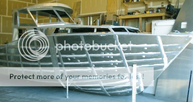
This brow is very rounded, (Plan View) the radius is nearly or perhaps the same as 1/2 the cabin top's width because the circle that is described by the brow is nearly tangent to both sides of the cabin top. The hull weld print through lines are sanded flat- I'd guess the yacht like hull will be painted?
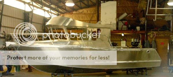
Here is a brow that is much taller than the narrow 'visor' types and begins to give the cabin almost a flying bridge type of proportion. I personally like the upper brow line in relationship to the sheer's 'leap line' or the surge upward of the sheer, while the hollow up-swept brow line seems to compliment that lower curve. To me this is a most attractive and accomplished set of boat lines- whoever drew these sweet lines, with their nice harmony, is a very artistic designer.
One very nice feature to my eye is the tighter cylindrical corners transitioning the main forward brow's curve (a cylindrical section in itself) to the side planes which are more planar, or even flat in Plan view? This rolled corner is a very sweet looking detail to me.
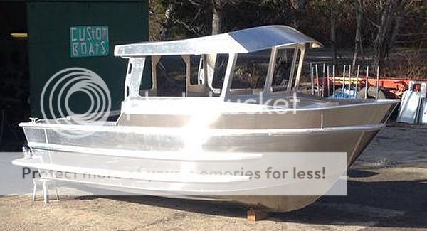
Here is a hull that astglenn could note. The bulwarks forward are a very tall toe railing, with a trunk cabin rising inside the walk-around deck or sheer clamp. This hull's bulwarks contributes a great deal to the sheer line's shape, even though it is an added piece of plate.
The brow is nicely curved but finished on the two side transitions by a simpler mitered joint instead of the more complex smaller diameter cylindrical section. But it does show a means to finish this design and visor element in a simple but clean method. Also important in this picture is the much greater rake or angle to the waterline plane of the brow. This highly increased rake (more angle backward) over the photo above shows the effect of what a small detail in design mean in the final look of your cabin.

astglenn, I hope you'll note this boat's sheer line is somewhat flat if there were no added bulwarks forward? Again we can see the look of the boat is drastically effected by the addition of some forward plates at the original deck line?
This is an even more simplified brow, its there, they' didn't skip the brow but its faceted or flat plates like the windscreen. The rake, the lack of curves and the mitered or butted shape intersections all contribute to this boat's differences from the immediate images above.
Why look at all this? Well.... I'm introducing the final looks so the following discussion of the underlying geometry will have a connection to the real world- these boats shown above- and therefore your own effort to draw a cabin might explore half dozen different curves, styles and rakes of brow pieces as you draw your cabin.
Next let's look at some geometry as regard the brow on the cabin above the window band's windscreen.
Cheers,
Kevin Morin
Kenai, AK
I'm going to get back to the original topic so it is posted on the site.
We were discussing the Brow as a design aspect and in some posts we'll look at the geometry that defines the brow but for now a few more images from around the web showing the different looks a Brow conveys to a boat's overall lines.
This brow is very rounded, (Plan View) the radius is nearly or perhaps the same as 1/2 the cabin top's width because the circle that is described by the brow is nearly tangent to both sides of the cabin top. The hull weld print through lines are sanded flat- I'd guess the yacht like hull will be painted?
Here is a brow that is much taller than the narrow 'visor' types and begins to give the cabin almost a flying bridge type of proportion. I personally like the upper brow line in relationship to the sheer's 'leap line' or the surge upward of the sheer, while the hollow up-swept brow line seems to compliment that lower curve. To me this is a most attractive and accomplished set of boat lines- whoever drew these sweet lines, with their nice harmony, is a very artistic designer.
One very nice feature to my eye is the tighter cylindrical corners transitioning the main forward brow's curve (a cylindrical section in itself) to the side planes which are more planar, or even flat in Plan view? This rolled corner is a very sweet looking detail to me.
Here is a hull that astglenn could note. The bulwarks forward are a very tall toe railing, with a trunk cabin rising inside the walk-around deck or sheer clamp. This hull's bulwarks contributes a great deal to the sheer line's shape, even though it is an added piece of plate.
The brow is nicely curved but finished on the two side transitions by a simpler mitered joint instead of the more complex smaller diameter cylindrical section. But it does show a means to finish this design and visor element in a simple but clean method. Also important in this picture is the much greater rake or angle to the waterline plane of the brow. This highly increased rake (more angle backward) over the photo above shows the effect of what a small detail in design mean in the final look of your cabin.
astglenn, I hope you'll note this boat's sheer line is somewhat flat if there were no added bulwarks forward? Again we can see the look of the boat is drastically effected by the addition of some forward plates at the original deck line?
This is an even more simplified brow, its there, they' didn't skip the brow but its faceted or flat plates like the windscreen. The rake, the lack of curves and the mitered or butted shape intersections all contribute to this boat's differences from the immediate images above.
Why look at all this? Well.... I'm introducing the final looks so the following discussion of the underlying geometry will have a connection to the real world- these boats shown above- and therefore your own effort to draw a cabin might explore half dozen different curves, styles and rakes of brow pieces as you draw your cabin.
Next let's look at some geometry as regard the brow on the cabin above the window band's windscreen.
Cheers,
Kevin Morin
Kenai, AK
kmorin
-
kmorin
- Donator 08, 09, 10, 11, 12, 13, 14, 15, 16, 17, 18, 19, 20, 21, 22, 23, 24
- Posts: 1743
- Joined: Mon Aug 18, 2008 1:37 am
- 15
- Location: Kenai, Alaska
Re: Pilot House; Design-Build
The geometry of the brow is a series of interesting cylindrical sections. If a cylinder is cut lengthwise, it will produce a uniformly rolled surface and it there were two or more of these surfaces, they can be intersected again in countless angles of intersection.
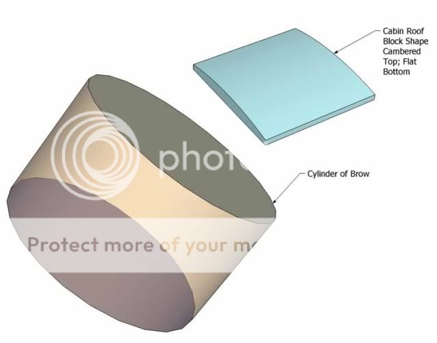
Here is a blue cabin top with camber, and for the sake of making it a solid there's a vertical edge on all sides . To the left is a brown cylinder, the entire cylinder is shown so the idea of a section is more obvious, the purpose is to visualize the easy geometry of the brow's pieces.
One key point is the radius of the cylinder has been closely matched to the cabin top width to achieve and intersection that extends forward of the brow, a distance already planned.

In this image the two geometric objects, the brow's theoretical cylinder and the cabin top's cylindrical section (due to camber on top) are
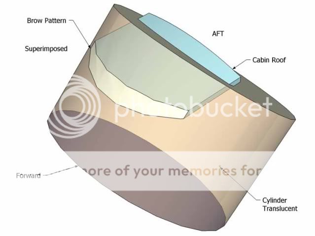
By making the brow cylinder 'see through' again we can see how these two sets of surfaces intersect.
[NOTICE: in order to make the SketchUP software model faster- years ago when I made these sketches I left the curves at a very coarse faceting setting. So the curves in most of these images will be 'faceted' or have angle points or line segments instead of smooth curves we'd expect to see like the photographs in the previous posts.]
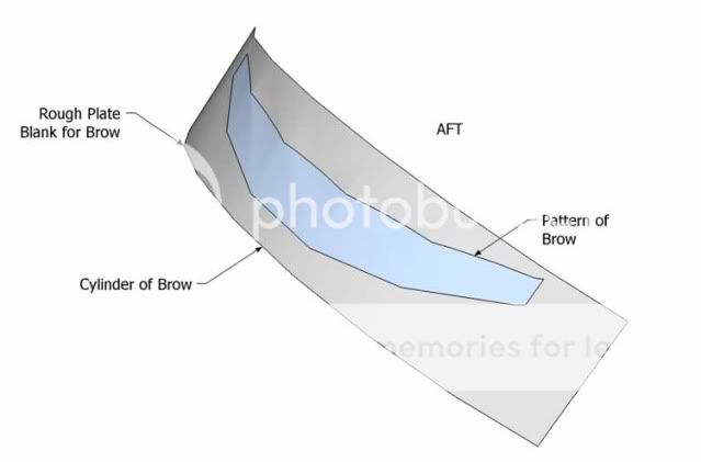
We really don't need the whole cylinder anymore to see the 'blank' piece of plate or sheet that is used to form the brow. So here that is trimmed to a smaller piece of the cylinder, and the cabin top is gone to leave us the brow's pattern image in blue.

To clarify the images in several views, here's a sketch of the same cabin top with a brow added in different angles of view. The idea I'd hoped to convey is the brow (here shown below the cabin top) can be considered just a plate draped over a curve cut in the cabin top- held at an angle to the cabin top in Profile View.
There are some other design considerations and we'll look at them next.
Cheers,
Kevin Morin
Kenai, AK
Here is a blue cabin top with camber, and for the sake of making it a solid there's a vertical edge on all sides . To the left is a brown cylinder, the entire cylinder is shown so the idea of a section is more obvious, the purpose is to visualize the easy geometry of the brow's pieces.
One key point is the radius of the cylinder has been closely matched to the cabin top width to achieve and intersection that extends forward of the brow, a distance already planned.
In this image the two geometric objects, the brow's theoretical cylinder and the cabin top's cylindrical section (due to camber on top) are
By making the brow cylinder 'see through' again we can see how these two sets of surfaces intersect.
[NOTICE: in order to make the SketchUP software model faster- years ago when I made these sketches I left the curves at a very coarse faceting setting. So the curves in most of these images will be 'faceted' or have angle points or line segments instead of smooth curves we'd expect to see like the photographs in the previous posts.]
We really don't need the whole cylinder anymore to see the 'blank' piece of plate or sheet that is used to form the brow. So here that is trimmed to a smaller piece of the cylinder, and the cabin top is gone to leave us the brow's pattern image in blue.
To clarify the images in several views, here's a sketch of the same cabin top with a brow added in different angles of view. The idea I'd hoped to convey is the brow (here shown below the cabin top) can be considered just a plate draped over a curve cut in the cabin top- held at an angle to the cabin top in Profile View.
There are some other design considerations and we'll look at them next.
Cheers,
Kevin Morin
Kenai, AK
kmorin
-
kmorin
- Donator 08, 09, 10, 11, 12, 13, 14, 15, 16, 17, 18, 19, 20, 21, 22, 23, 24
- Posts: 1743
- Joined: Mon Aug 18, 2008 1:37 am
- 15
- Location: Kenai, Alaska
Re: Pilot House; Design-Build
We were at the discussion of the brow, and while you may feel this is too esoteric to spend time explaining or discussing (??  ) I think the photos above showing different boats' brows and the impact on the looks of the boats makes this worth exploring?
Thankfully, anyone who's in disagreement with my reasons for posting this can click away and avoid the next few posts about this detail of cabin design.
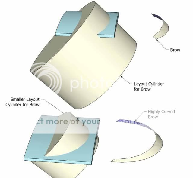
Above I'd mentioned that the radius of the brow is set by the radius (distance aft the windscreen) the arc was drawn or designed. Here, a pair of cylinders of different radii show the effects of the very gently curing brow (longer radius) from one that is nearly semi-circular where the radius is much shorter.
Maybe you'll recall this image of the compass bar/trammel used to layout this curve? IF the radius (circle's) center were behind the cabin top's after edge- farther and farther- the radius becoming larger and larger means the curve would become softer and less circular.
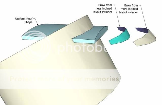
Also from the photos above we saw examples of the angle of the brow to the cabin top or to the waterline? Here we're looking at one fixed camber with one fixed radius but different angles of rake of the brow and what that series of changes could mean to the looks of the cabin.

Let's combine rake and radius to see the combinations' effects on the brow. This image begins to explore the countless combinations of these two design variables- angle to the waterline in Profile View and Radius of the Brow in Plan View, to start defining the effects of these two related decisions in your design.
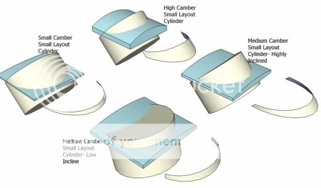
Here is the same idea as the image above with more selections and combinations of the rake and radius. It might be a worthwhile exercise if you're still seeing a fog in this thread?? to compare these two sketches to the photos posted above showing different brows. I hope this makes sense and helps to inform you ( a little more) what is involved in the design process of the cabin brow?
Cheers,
Kevin Morin
Kenai, AK
Thankfully, anyone who's in disagreement with my reasons for posting this can click away and avoid the next few posts about this detail of cabin design.
Above I'd mentioned that the radius of the brow is set by the radius (distance aft the windscreen) the arc was drawn or designed. Here, a pair of cylinders of different radii show the effects of the very gently curing brow (longer radius) from one that is nearly semi-circular where the radius is much shorter.
Maybe you'll recall this image of the compass bar/trammel used to layout this curve? IF the radius (circle's) center were behind the cabin top's after edge- farther and farther- the radius becoming larger and larger means the curve would become softer and less circular.
Also from the photos above we saw examples of the angle of the brow to the cabin top or to the waterline? Here we're looking at one fixed camber with one fixed radius but different angles of rake of the brow and what that series of changes could mean to the looks of the cabin.
Let's combine rake and radius to see the combinations' effects on the brow. This image begins to explore the countless combinations of these two design variables- angle to the waterline in Profile View and Radius of the Brow in Plan View, to start defining the effects of these two related decisions in your design.
Here is the same idea as the image above with more selections and combinations of the rake and radius. It might be a worthwhile exercise if you're still seeing a fog in this thread?? to compare these two sketches to the photos posted above showing different brows. I hope this makes sense and helps to inform you ( a little more) what is involved in the design process of the cabin brow?
Cheers,
Kevin Morin
Kenai, AK
kmorin
-
kmorin
- Donator 08, 09, 10, 11, 12, 13, 14, 15, 16, 17, 18, 19, 20, 21, 22, 23, 24
- Posts: 1743
- Joined: Mon Aug 18, 2008 1:37 am
- 15
- Location: Kenai, Alaska
Re: Pilot House; Design-Build
So far, we've looked at the brow in detail because I've argued it was a very important little piece of metal. I've shown why I think its shape is so influential for the cabin's look in regard the boats lines. Now we'll look a bit at the layout or scribing and marking of the cuts. Not the only way to do this work, certainly, and as most one off home builders don't use software to develop surfaces; I'm showing here some rudimentary methods of marking so that cuts with hand power tools could result in clean lines and finely edged welds.
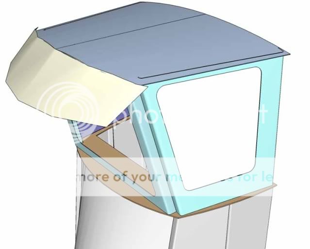
By holding a plate/sheet piece to the cut arc on the top of the cabin, the edge of the brow can be marked reaching behind or below the intersection of the two pieces when held in this position. I've drawn the top edge cut, but in previous views you can see that any material thin enough to bend without rolling and extending above and below the cabin top will work as a blank.
A means to get the angle or rake correct is to put a set of temporary 'sticks of aluminum' tacked to the top- where one stick is at the angle in Profile View the other holding it up like a leg. Or; cut ply wedges and hold them to the brow blank while its in place. All work related techniques depend on the 'crews' size 1 set to lots of sets hands means different methods make sense.
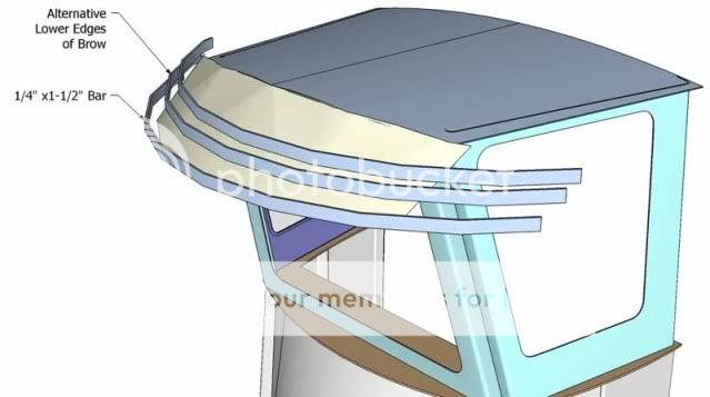
Once the blank is cut and tacked up... if the cabin is built on the shop floor, which may not be the case, its possible to strike the lower brow curve using a straight edge and several ares shown here. The image illustrates the method of striking the lower line by holding the aluminum bar extrusion at differing distances (width of the brow vertically) and when this is held in place the bar may be vertical or raked slightly and again these intersecting cylinder will create a VAST , large number, huge amount of different curves of intersections.
If the reader wanted to correlate this very unassuming image to the work done to build the boats in the photos above, then click back and forth and the relational geometry will hopefully start to emerge? Some of the brows we've seen have nearly horizontal lower edges, but others have a echoing curve upward in the transverse sweep. This is where some of the beauty of this shape becomes a subtle set of interrelated intersecting curves.
Regardless how refined the shape- these ideas shown are the basic building blocks for laying out and building your own version of an attractive (to you) cabin brow.
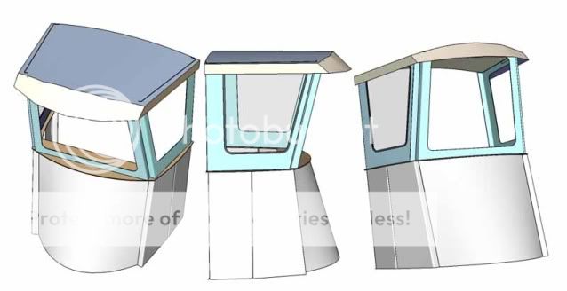
While not an exhaustive exploration of this windscreen covers' shapes, we've explored the three main contributions to the brow and cabin top shape. First is the camber of the cabin top as it could contribute to the brow's shape. Next is the combinations of the Plan View radius of the brow and the Profile View rake so the brow. These elements are the main influences on this functional but aesthetically pleasing piece of metal that shades the windscreen, sheds water and stylizes your cabin.
but what about some corners and hand rails?
Cheers,
Kevin Morin
Kenai, AK
By holding a plate/sheet piece to the cut arc on the top of the cabin, the edge of the brow can be marked reaching behind or below the intersection of the two pieces when held in this position. I've drawn the top edge cut, but in previous views you can see that any material thin enough to bend without rolling and extending above and below the cabin top will work as a blank.
A means to get the angle or rake correct is to put a set of temporary 'sticks of aluminum' tacked to the top- where one stick is at the angle in Profile View the other holding it up like a leg. Or; cut ply wedges and hold them to the brow blank while its in place. All work related techniques depend on the 'crews' size 1 set to lots of sets hands means different methods make sense.
Once the blank is cut and tacked up... if the cabin is built on the shop floor, which may not be the case, its possible to strike the lower brow curve using a straight edge and several ares shown here. The image illustrates the method of striking the lower line by holding the aluminum bar extrusion at differing distances (width of the brow vertically) and when this is held in place the bar may be vertical or raked slightly and again these intersecting cylinder will create a VAST , large number, huge amount of different curves of intersections.
If the reader wanted to correlate this very unassuming image to the work done to build the boats in the photos above, then click back and forth and the relational geometry will hopefully start to emerge? Some of the brows we've seen have nearly horizontal lower edges, but others have a echoing curve upward in the transverse sweep. This is where some of the beauty of this shape becomes a subtle set of interrelated intersecting curves.
Regardless how refined the shape- these ideas shown are the basic building blocks for laying out and building your own version of an attractive (to you) cabin brow.
While not an exhaustive exploration of this windscreen covers' shapes, we've explored the three main contributions to the brow and cabin top shape. First is the camber of the cabin top as it could contribute to the brow's shape. Next is the combinations of the Plan View radius of the brow and the Profile View rake so the brow. These elements are the main influences on this functional but aesthetically pleasing piece of metal that shades the windscreen, sheds water and stylizes your cabin.
but what about some corners and hand rails?
Cheers,
Kevin Morin
Kenai, AK
kmorin
-
kmorin
- Donator 08, 09, 10, 11, 12, 13, 14, 15, 16, 17, 18, 19, 20, 21, 22, 23, 24
- Posts: 1743
- Joined: Mon Aug 18, 2008 1:37 am
- 15
- Location: Kenai, Alaska
Re: Pilot House; Design-Build
We're getting closer to having a full cabin design build method shown here at the Forum, where it belongs. Let's continue with some more details and start by finishing the brow's outboard corners.
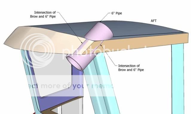
IN a few of the boat photographs posted above, the brow is mitered or butted to the side brow plates, and that is not unattractive but also isn't quite as elegant as the forward curved surface curving into the side surface.
This image summarizes the geometry: a segment of a cylinder of tighter/smaller radius. All the curved corners we've seen are is this segment of another cylinder. Often in small cabins this piece can easily be cut from a piece of pipe, as I show here- 6" pipe.
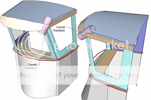
This image just shows the pipe surface in its finished orientation as part of the two adjoining surfaces but leaving the entire pipe visible so the origin of that piece is recalled in this sketch. In the image (next) above I left the two plate surfaces (browns) to show how all three intersect on tangents to the pipe's wall.
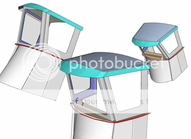
Back to our cabin overall from different points of view, the added detail of a curved brow corner transition from the side to forward surfaces is shown here, and the blend of these three surfaces seems a nice refinement to me.
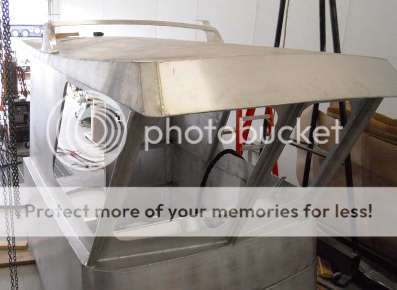
Here is one such pipe wall segment used in the brow of a 25'er's cabin top. Note the brow extends down from the top but there is a lower lining or 'sub cabin top' structure in this design as well? I hope this corner image helps to show the sketches in real life construction?

The upper edge of the pipe wall segment is not trimmed in this progress photo of this cabin's brow construction. One important point to make about this cabin design- the lines are subtly curved fore and aft- for the most part. This implies a vast increase in work, laying out and cutting the curves (#1); Fairing the cuts, and tacking up long sweet seams that could be bent (#2); and welding a lot of seams in relatively thin materials that is a major time contribution if you're coming to this work for the first time.
I'm not suggesting that this design is appealing to the wider boating audience, my Skipper (here) had lived on the water for his entire life, was very esoterically concerned about every design detail and was vocal and influential about every curves' nature and extent. He was a pleasure to work for in design and building as he would spend time considering and responding to the aesthetics of the work, making my work for him a nice challenge to meet. Not all owners are as concerned with the overall look of their craft and therefore lots of work was done in this cabin that might be considered too expensive for other boats?
(Generally you will not find this kind of one to one design build from the major builders as they need to keep to a schedule to stay in business, I'm not in business and only did this project for the enjoyment of building so I'm not saying that the extra level of effort shown would be economically realistic unless the owner wanted to pay for that extra time.)
I agree with anyone who says " it took lots more time" ( Read: Mo' $$$$ !!) but I'm personally pleased with the results of the extra effort and if you're building your own cabin; I think its worth your time to explore these details to consider if they're worth your time.
Let's keep going by finishing some other details of cabin building.
Cheers,
Kevin Morin
Kenai, AK
IN a few of the boat photographs posted above, the brow is mitered or butted to the side brow plates, and that is not unattractive but also isn't quite as elegant as the forward curved surface curving into the side surface.
This image summarizes the geometry: a segment of a cylinder of tighter/smaller radius. All the curved corners we've seen are is this segment of another cylinder. Often in small cabins this piece can easily be cut from a piece of pipe, as I show here- 6" pipe.
This image just shows the pipe surface in its finished orientation as part of the two adjoining surfaces but leaving the entire pipe visible so the origin of that piece is recalled in this sketch. In the image (next) above I left the two plate surfaces (browns) to show how all three intersect on tangents to the pipe's wall.
Back to our cabin overall from different points of view, the added detail of a curved brow corner transition from the side to forward surfaces is shown here, and the blend of these three surfaces seems a nice refinement to me.
Here is one such pipe wall segment used in the brow of a 25'er's cabin top. Note the brow extends down from the top but there is a lower lining or 'sub cabin top' structure in this design as well? I hope this corner image helps to show the sketches in real life construction?
The upper edge of the pipe wall segment is not trimmed in this progress photo of this cabin's brow construction. One important point to make about this cabin design- the lines are subtly curved fore and aft- for the most part. This implies a vast increase in work, laying out and cutting the curves (#1); Fairing the cuts, and tacking up long sweet seams that could be bent
I'm not suggesting that this design is appealing to the wider boating audience, my Skipper (here) had lived on the water for his entire life, was very esoterically concerned about every design detail and was vocal and influential about every curves' nature and extent. He was a pleasure to work for in design and building as he would spend time considering and responding to the aesthetics of the work, making my work for him a nice challenge to meet. Not all owners are as concerned with the overall look of their craft and therefore lots of work was done in this cabin that might be considered too expensive for other boats?
(Generally you will not find this kind of one to one design build from the major builders as they need to keep to a schedule to stay in business, I'm not in business and only did this project for the enjoyment of building so I'm not saying that the extra level of effort shown would be economically realistic unless the owner wanted to pay for that extra time.)
I agree with anyone who says " it took lots more time" ( Read: Mo' $$$$ !!) but I'm personally pleased with the results of the extra effort and if you're building your own cabin; I think its worth your time to explore these details to consider if they're worth your time.
Let's keep going by finishing some other details of cabin building.
Cheers,
Kevin Morin
Kenai, AK
kmorin