Remodeling Thread

Mods and custom builds
kmorin
Donator 08, 09, 10, 11, 12, 13, 14, 15, 16, 17, 18, 19, 20, 21, 22, 23, 24
Posts: 1743
Joined: Mon Aug 18, 2008 1:37 am
15
Location: Kenai, Alaska

Remodeling Thread

#1

Post by kmorin »

We've had lots of remodels on the Forum and have a concurrent thread on stand-up or walk-around type cabins going as a 'How To' explanation.

I think we should have a general remodel thread as well? To begin this thread I'll take an used hull and make some hopefully thought provoking remarks that explore the various types of cutting away, adding too ideas that might be used to guide your design.

As a handy example astglenn has a surplus boat that has a flat sheer, is I/O powered but is an open hull with few creature comforts since it appears to have been a day boat, working as a buoy tender? and therefore not designed to have creature comforts that would make it enjoyable for an offshore fishing boat.

We've talked on the other cabin thread about the boat, there are pictures 'next door' but the subject of a stand up (free standing, walk-around) cabin really doesn't apply there. This boat needs a 'fort' style cabin integrated to the hull at the forward 1/2 of the hull. So that's the first remodel I'll try to discuss in this thread.

Before going to a cabin for the boat, I think a discussion of the forward 1/2 the hull is worth holding?

Image

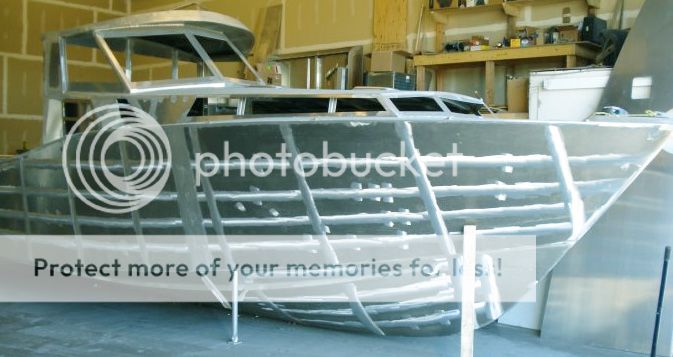
If you'd been reading along the cabin topic I posted the image copied from the net (don't know the builder or designer) and I'm posting it here to point out the element of the boat I'd like to begin to discuss.

The sheer is fairly flat not much raise to the bow, not much shape in regard curving in the Profile View. The shape of the forward part of the hull is give almost exclusively by the bulwarks; the two arc top plates welded to the deck at the sheer edge in the forward 1/2 or so of this boat.

This boat uses almost plumb shapes, the plates are almost vertically aligned above the sheer line. In the Body Section view they would be almost vertical as near as I can see in this photo taken outboard in Profile of the boat. In the forward 1/3 of these bulwarks they may lean or rake forward (?) a bit but in Body Section they seem relatively plumb?

If astglenn's boat had such bulwark plates added to his straight line sheer- the forward bow would be raised in Profile View, changing the boat's entire look. If the bow as is presently build is driven into a head sea, it will lift but the water may come over the bow but it the bow were raised -using bulwark plates added to the flat sheer, the bow will become deeper. A deeper bow will displace more water than a shallower bow of the same flam/lean/side angle just a deeper beer glass holds more than a shallow one.

So one thing to consider in a remodel of the type we're discussing is the relatively easy task of adding to the sheer? Bulwarks would help 'dry out' the bow and provide more lift to the same before boarding a 'green one' over the bow.

Some boats use their bulwarks to create a deep walkway along the sheer, forward along side the main cabin (or fort). Others deck all the way over the bulwarks and achieve massive volume increase inside the forward 'trunk' cabin in the bow.

Image

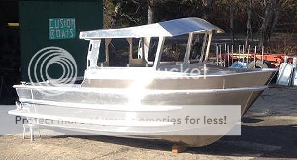
A repeat image post, again downloaded from the inter-net's hoard of boat images, but the reason for this pic is to show an example of the bulwark line being decked from side to side. Now the boat is much larger than its comparison above, and therefore provides much more interior volume anyway.... but... the point I'm making is to call attention to a remodel of a small boat that could enclose all the volume inside and under a set of added bulwarks.

So please line your eye up with the first buffed/sanded line down from the sheer. Call this the 'deck line' if the boat were to have a deck inside a bulwark; and then call the top of the sheer just the top of the bulwarks? That volume above the upper most buffed line (below the sheer) is the gain in volume for the cabin of this boat. IF that were added to the forward volume of the other boats shown here??? the room inside would be MUCH larger and the bow would shed much more 'big water' and lift much higher- not wallow if the deck were filled because it would shed compared to scooping of the bulwark and deck design. All reasonable design questions to explore, IMO.

Once this is studied a few times, perhaps a bit of pencil to paper (I'm not completed with my sketches on the subject) it will become pretty obvious that #1 adding bulwarks could be done to increase the bow volume for pitch of the bow upward (sea keeping) and if they were decked for side to side ??? these same plates may become the outside of the new lower or trunk cabin while still improving the lines of the boat? Finally the living volume or stowage space at least could be radically increased over the flat sheer boat without a trunk and especially without a trunk that reaches from sheer to sheer.

Image

I posted this image on the cabin build thread as well; here I'm calling attention to the bulwarks. Because of the coloration of bright (un-etched!!! :deadhorse: ) metal in this photo you can see (imagine?) what might happen if the bulwarks were the side of the cabin! I know you'd be walking forward on top of the trunk as the new deck .... but a short toe rail would make it safe and the interior volume gain that is 'sort of- kind of' shown in the photos' lighting may help to show what my sketches will attempt to explore.

The exploration of bulwarks as a design element needs to include- #1 are these plates leaned out? #2 are they plumb? #3 are they leaned in? All of these provide different shapes and looks. #4 Are they along the outside and above a deck with a cabin structure rising inboard of the narrow walking deck? #5 Are the bulwarks decked side to side regardless of the shape in the first question above? #6 And if they are any of these (#'s 1 to 5 above) design decisions; what does that leave us regarding a cabin structure?

More to follow...

Cheers,
Kevin Morin
Kenai, AK
Last edited by kmorin on Tue Mar 24, 2015 4:06 pm, edited 1 time in total.
Reason: poor writing; attempted corrections
kmorin
astglenn
Posts: 12
Joined: Wed Mar 18, 2015 8:18 am
9

Re: Remodeling Thread

#2

Post by astglenn »

Kevin. As I am following along, I am learning to use the correct terms for the sections and components. Does "Bulwark" describe the vertical extension of the outer hull above the deck line for the entire longitudinal section, or does it describe only that condition when it occurs forward of a certain station? Please bear with me as I hack my way through this.

This plan form IMHO, for what are my prime list of preferences are, would be a nearly perfect design. The additional volume at the bow really reminds me of a "Nordic" Trawler. I am a big fan of a lot of freeboard at the bow. If it is narrow, please Lord let there be a reasonable flair. That additional height above the water line and expanded volume really have the most practical benefit at the least compromise in my set of requirements. The ability to access the bow, without any acrobatics or heroics is a prime concern to me. The wide "gunnel"?? that my existing hull carries makes a useful and uncomplicated pathway forward. The elevation transition from the deck to the Gunnel is fairly easily to accomplish by mortals when the grab rail at the rear of the existing house is used. My reason for laying the top of my existing house as an inward taper, rather than simply carrying the walls to a 90 degree corner at the roof intersection, was to support the most painless transition from the deck to the bow. Getting that damned corner gathered at the front of the house was a bit of a pain. The ability to access that bow section, for my uses, is a real design driver. A true walk around design would be heaven in terms of accessibility, but I just don't feel that a walk around provides the level of forward closure that I feel super comfortable with. I have seen several however, mostly vintage "Carolina" style CC's and cuddy's that looked pretty burly from a distance.


Image
This is pretty much what I would have Kevin build for me if I was so lucky. It is what I would build myself, if Kevin was so lucky! It looks as though there would perhaps be some extension of the length of the house over what I currently have. If there was some way to get a head figured into a design like this, that would be heaven.

Image
While not great, the bow can be accessed reliably under actual at sea conditions. There is not a lot of forward deck, but it is prime real estate for me.
kmorin
Donator 08, 09, 10, 11, 12, 13, 14, 15, 16, 17, 18, 19, 20, 21, 22, 23, 24
Posts: 1743
Joined: Mon Aug 18, 2008 1:37 am
15
Location: Kenai, Alaska

Re: Remodeling Thread

#3

Post by kmorin »

astglenn, yes the bulwarks are the short 'side extension' upward at the sheer. They will be the subject of some images I'm sketching now.

The concept of converting your boat to something like the one shown above- is a series of steps listed below. Most of these steps require design considerations that aren't fully made, so this thread is to explore those decisions, help you evaluate what is needed to make informed choices and then to draw what those add up to become for your hull.

#1 cut out the existing deck within a 16" or so of the sheer, to form a longitudinal instead of a deck- curved uniformly within a given distance of the sheer/rub rail/gunwale's outer edge.
#2 add a bulwark to the upper most edge of the sheer, and flam (lean it out; like flair but not curved in Body Section /cross section/station view) that bulwark outward to increase lift of the bow (pitch of the hull upward viewed from the side/Profile View) and to vector water outward away from the hull when in head seas.
#3 deck all the way across, or very nearly the full ht of the bulwarks; which, because they now are near the deck are not bulwarks but become trunk cabin sides (!) Definition of bulwark is usually agreed to be a short wall of hull above the deck- solid railing so to speak.
#4 Now the deck is raised forward providing very tall sitting and therefore 'squatted walking' volume forward
#5 With the deck reaching aft 5-6' a sitting area/bunks/stowage/sitting down head compartment can be built in this forward volume
#6 The new helm can hang from the aft edge of the new raised deck.... raising the helm like a 'brow' off the new raised deck.
#7 The windscreen can sit or base on the new raised deck, regardless of rake,
#8 The after cabin sides can be mounted to raised side decks that are merely a step up from the after (existing) sheer clamp/guard deck/plate at the sheerline, providing access forward.
#9 The cabin top will be closer to the new raised deck and that relieves the need of an outside rail until the brow forward edge- form there forward a pulpit type rail as already shown would make bow work safe.

#10 inside one or the other side wall of the new cabin, you can frame a standup head "closet", which can double as a hanging locker for gear when not in use? So a sit down head forward in the new forecastle/trunk cabin area or a stand up head in the after bulkhead of a new cabin are both possible in your hull.

These steps are what I've planned to illustrate for this thread. Looking at the hull's low freeboard forward I think that maintaining the existing deck without adding a 'leap' or 'step' or swept upward bow plate (bulwark regardless of sheer line style choice) will be too low to have much of a forward trunk cabin area. So, I'm advocating the consideration raising the entire forward bow area as verbally described.

At this time the only image I can offer is an un-built, design exercise boat I've drawn. The reason for posting the somewhat different hull from yours...... is to look at the idea of a raised trunk in terms of changing your boat.

Image

This image of a model only, shows a raised green bulwark-like panel that is decked over in a gray deck, forming a huge forward volume in an 18' skiff. The beam is extreme and the shape is an attempt to put a house on an 18'er that was 'livable' for two people using this size skiff.
Why I post it here is to show the concept of larger bow volume as described in text above. The proportions wouldn't be the same and that will make these images somewhat less useful but they're what I have to post today.

Image

Outboard Profile View shows the lines of the skiff's sheer are not obvious regarding the raised deck. The stepped or leaped sheer (jogged sheer?) has a color change to show this design element (green) and there is an inner cockpit bulwark (gold/brown) aft making the cockpit or deck area deeper but an attempt has been made to sort of fool the eye into seeing the gray sides as relatively lower than the total side height off the water.

Image

This bow on or Body Section View shows the stations imposed on the colored hull panes. Notice the green upper topside panel has more flam- outward lean- than the the lower topsides? (sometimes referred to a flare- which more accurately used to describe this angle of lean of a curved body section panel I think we have a discussion of these terms and illustrations somewhere on the Forum?)

This performs; as the waterline rises toward the sheer, that same water will displace more per inch of immersion (increasing pitch by the bow- lift) & that same shape will vector the water away from the bow more than the angle of the topsides below.

What is lost in this design in the well deck area created by deep bulwarks forward What is gained is the habitable space below, higher sea state running, simplification of the build, and very reduced bow load of free water cupped on deck by the bulwarks if the boat ships a big green pacific roller onto her foredeck area.

astglenn, I'm going to put up a series of sequential sketches to look at the various choices that are implied in this post combined with these images. To do that I've sketched the existing hull (eyeballing the lines not having any 3D digital files handy!) I'm not suggesting the upper cabin in these images will be useful in your remodel, the only part of these I'm showing is that combination of raised forward topsides and decking that completely side to side as shown. Please ignore the single post cabin!!! it was in the design exercise's SOR and is not part of our discussion- like the stand alone or dog house cabin thread these are illustrations I had handy so they're being used to make a point not suggest your eventual design.

Cheers,
Kevin Morin
Kenai, AK
kmorin
kmorin
Donator 08, 09, 10, 11, 12, 13, 14, 15, 16, 17, 18, 19, 20, 21, 22, 23, 24
Posts: 1743
Joined: Mon Aug 18, 2008 1:37 am
15
Location: Kenai, Alaska

Re: Remodeling Thread

#4

Post by kmorin »

astglenn, did you post the overall dimensions of the Monarch hull? bow to stern tip to tip (LOA), widest point of the hull at the sheer (B0A) and the listed 20degs of the bottom deadrise (!!?) what is the inner and outer chine BOA? (bottom width) I"m trying to get an approximate model to use for illustrations, but don't seem to find real live full dimensions?

Also the depth from chine to sheer line, and any other dimension that's handy will be useful making a model of the form.

Cheers,
Kevin Morin
Kenai, AK
kmorin
astglenn
Posts: 12
Joined: Wed Mar 18, 2015 8:18 am
9

Re: Remodeling Thread

#5

Post by astglenn »

Kevin. I went out in the shop and dragged a tape around. The Bottom is a tad tough to get at in the beam area due to trailer bunks but I think we are within 1/4" of being accurate there. . Here is what I have:

LOA 21'10"

BOA 92 1/2" ( Measured at top of beam and excludes rubber bumpers)

Bottom width at beam 43 1/2"

Chine to top line at beam 32 1/2"

Chine to top line at transom 28"

Hopefully this is what you asked for and I have not failed in the data acquisition phase.
kmorin
Donator 08, 09, 10, 11, 12, 13, 14, 15, 16, 17, 18, 19, 20, 21, 22, 23, 24
Posts: 1743
Joined: Mon Aug 18, 2008 1:37 am
15
Location: Kenai, Alaska

Re: Remodeling Thread

#6

Post by kmorin »

astglenn,
would you confirm the OVERALL distance (plumb bob to ground under the chine) measured on the ground from the outer chine to outer chine? 43" seams narrow? Beam Over All is an outside dimension like you list of 92" at the sheer inside the rubber extrusions. BOA of the bottom is taken about where the engine cover is in the pic, on the ground or pavement using plumb bobs or dropping a little rock if it will not bounce.

Cheers,
Kevin Morin
Kenai, AK
kmorin
astglenn
Posts: 12
Joined: Wed Mar 18, 2015 8:18 am
9

Re: Remodeling Thread

#7

Post by astglenn »

Kevin. The out to out measurement of the chines, at the beam (widest station) is 87" Sorry for the confusion.
kmorin
Donator 08, 09, 10, 11, 12, 13, 14, 15, 16, 17, 18, 19, 20, 21, 22, 23, 24
Posts: 1743
Joined: Mon Aug 18, 2008 1:37 am
15
Location: Kenai, Alaska

Re: Remodeling Thread

#8

Post by kmorin »

astglenn, here are some initial images of the hull, taken from the photos, your dimensions and my opinion of anything you haven't already given specifically in answer to my previous questions.

As with most sketches the colors are to denote layers or objects and not a paint scheme- just to help separate pieces of the hull. The scale lines may be visible but I'm converting to postable images (maybe that's hostable images?) and not providing online plans- just showing concepts for education and discussion, please don't anyone think that welder is responsible for my ideas or opinions and he's not rich so trying to sue him will not help your frustration- with me! If you're reading here and don't understand that a discussion is being held!!! Then Please Re-Read all these posts to grasp this fact.

This is not the only way to design a modification of this or any boat, and if you don't care for the lines, well I'm hoping you'll take away some of the basic ideas to draw your own? The model used is free to anyone who wants it, in Delftship Pro file format or AutoCAD format, it is not 'faired' ready to build- it is simply model for illustration purposes- please take that into account as we move along? All comments and suggestions are welcomed.

Image

This bow on shot shows a very shallow hull with a flat sheer that I mostly confirmed in the images posted. I've turned on the (new) 3Axis Planes display feature in this view to help show the relative view point and the grid of a 12" station set (centerline green glass panel at Keel plane) and a 6" butt lines set (below hull horizontal plane).

If any reading has not taken time to explore a post on the LInes of a Hull viewtopic.php?f=45&t=2558 it may help to get involved with the geometry and terms of the discussion? If there are any questions from that thread, don't hesitate to ask what I didn't explain or the missing info will probably make what I'm trying to show here... that much less clear?

Image

Body Plan or Body Section view (bow on) where both sides are shown along the entire hull. Some designers look at half of the bow view and half the stern view by showing the two sides or halves of this drawing with stations 1-6 on one side (right side?) and the 7-11 stations on the left side, not the only way to 'see' the stack of frames but it works. Here I wanted to show the boat's hull and bottom as I think they approximately relate to one another.

Image

Profile View (outboard profile) showing the flat plane and straight line of the sheer. NOt all that exciting but with some added plate this hull can become much more attractive and more seaworthy too.

Image

I'm not spending time to accurately model the existing small console and controls box or the foredeck as it really is. IF that were needed, we'd go though some fairly thorough measuring details and exercises to get the actual and factual shapes; but here all I'm trying to get across is the basic shape in rough scale of proportions.

Next we'll need to look at three sets of bow additions to the hull.

Cheers,
Kevin Morin
Kenai, AK
kmorin
kmorin
Donator 08, 09, 10, 11, 12, 13, 14, 15, 16, 17, 18, 19, 20, 21, 22, 23, 24
Posts: 1743
Joined: Mon Aug 18, 2008 1:37 am
15
Location: Kenai, Alaska

Re: Remodeling Thread

#9

Post by kmorin »

astglenn, first to explore some of what we've seen and how different proporsions of those plates added to your hull could look. The purpose of these images is NOT to provide THE design it is to explore A -any design.

So the images will mutate a bit, I'll add one item, then another and the go back and shift the proportions to the boat and explore the effects of some added metal to remodel the existing hull.

Image

A classic trunk cabin is rounded forward, and in this case the sides are vertical or plumb sided and the height off the deck is arbitrary, but the seating under this cover will be MUCH more than your stowage only forecastle/foc'sle.

Image

in this view a 12" or 14" tall vertical forward line trunk kind of looks like a Civil War Iron Clad? the purpose is just to show that a 10' strip curled on the deck with a 1/2 circle of 1/8" on top would begin to make some living space in the forward spaces now limited to gear stowage?

Image

however, if you used a couple more stips of plate 12" wide and 8' long , cut a couple curves on their edges, then the bow of the flat sheer begins to have some shape and this is what was done to some of the boats in the images we've posted and discussed. I'm not saying those boats used this hull but I am saying they added the plates I've shown here in purple to make their bulwarks, this helps reduce the trunk's profile AND to make deck access safer under way.

Image

Here we see a the Profile View with the purple bulwarks and even these fairly short (Iength) added plates begin to change the look of the hull?

Lets extend them aft? See if there are different proportions they might take with the sheer?

Cheers,
Kevin Morin
Kenai, AK
kmorin
kmorin
Donator 08, 09, 10, 11, 12, 13, 14, 15, 16, 17, 18, 19, 20, 21, 22, 23, 24
Posts: 1743
Joined: Mon Aug 18, 2008 1:37 am
15
Location: Kenai, Alaska

Re: Remodeling Thread

#10

Post by kmorin »

Astglenn, to keep this exploration of design going, I've stretched both the trunk and the bulwarks my purpose is to contrast what the original hull look like when these two items, without regard the rest of the cabin are stretched aft more than we saw above?

Image

First the short trunk and short bulwarks... then

Image
Then the longer set of both shapes on the same base hull.

Image

Last image in this set is the longer set of trunk and bulwarks in Profile View; I think the effect of the lines changes begin to show up?

Let put up a cabin on this (a fort like cabin) and see what might happen?

Cheers,
Kevin Morin
Kenai, AK
Last edited by kmorin on Thu Mar 26, 2015 10:09 pm, edited 1 time in total.
Reason: typo's as usual
kmorin
kmorin
Donator 08, 09, 10, 11, 12, 13, 14, 15, 16, 17, 18, 19, 20, 21, 22, 23, 24
Posts: 1743
Joined: Mon Aug 18, 2008 1:37 am
15
Location: Kenai, Alaska

Re: Remodeling Thread

#11

Post by kmorin »

astglenn,

we were looking at these images to being the process of exploring what some plate would do if added to your boat. We've added some and then stretched it and now here's a helm station (minimal in length) that is sitting on top of the trunk or the windscreen panels are on the trunk. I haven't look to see what the overall standing room is in this yet, I'm not at that point, I'm trying to illustrate how these different pieces of plate could change the look and feel of the boat.

Image

This is a 'fort' style house, where you have to climb on the gunwales to get past the window band. It just a quickie set of parts put up to explore the cabin's beginning surfaces. But I think this shows you how simple the boat's modifications could be... if you used this set of plates. (there are simple ways to layout and cut all this, even if you have an NC table, the CAD work might take longer than the hand layout?)

Image

Another outboard Profile View to show the changed looks of the original hull by adding some plate with a bit of shape forward.

I'll keep developing this model, and exploring other proportions, other parts and further illustrate the discussion: what can be added to the original hull to improve her looks and interior volume and can all that we add increase her seakeeping as well?

One thing that jumps off the page at me is that some aft coamings, along the sheer, could be cut to a sweet curve, increase the freeboard aft in the cockpit/deck area, and make her look a little be nicer at the same time.

Cheers,
Kevin Morin
Kenai, AK
kmorin
User avatar
goatram
Donator 08, 09, 10, 11, 12, 13, 14, 15, 16, 17, 18, 19
Posts: 1959
Joined: Wed Apr 09, 2008 11:53 pm
16
Location: Stanwood WA

Re: Remodeling Thread

#12

Post by goatram »

Looks good Kevin so far.

How to make the Bow have the Carolina Flare of a Clorox Bottle Boat? That would be sweet. And I would Mod My boat this Winter coming. If I could figure that out. :smitty:
John Risser aka goatram
33' RBW with twin 250 Hondas (Aliens)
2015 Ford F350 Dually
Master of R&D aka Ripoff and Duplicate
kmorin
Donator 08, 09, 10, 11, 12, 13, 14, 15, 16, 17, 18, 19, 20, 21, 22, 23, 24
Posts: 1743
Joined: Mon Aug 18, 2008 1:37 am
15
Location: Kenai, Alaska

Re: Remodeling Thread

#13

Post by kmorin »

goatram,

unfortunately that shape is curved in both directions (body section AND plan view) and unless you have an English Wheel and you're VERY good using it, that shape is not happening. But... there is a version of the shape that can be done simply in a welded (flat plate) developed surface boat.

While we can't wrap a hollow shape very easily without some stretch forming, we can create a shape that approximates the flare of the Carolina Offshore Hull with a flam that is made from a flat plate its a matter of the "chine cut" no different, in concept, than the topsides' chine cuts.

I'll be illustrating that in the next few posts.

Cheers,
Kevin Morin
Kenai, AK
kmorin
kmorin
Donator 08, 09, 10, 11, 12, 13, 14, 15, 16, 17, 18, 19, 20, 21, 22, 23, 24
Posts: 1743
Joined: Mon Aug 18, 2008 1:37 am
15
Location: Kenai, Alaska

Re: Remodeling Thread

#14

Post by kmorin »

To continue I had to check to see if my sketches were tall enough-they weren't so the profile was too low to stand on the deck in the cabin I'd drawn. Concept- OK; Dimension- not real world.

Here I've added to the first sketches by putting in a grid in Profile that shows waterlines up to 6' or so, this is from the keel, so the cabin is about 7' up. It still may need to be raised to give head room inside as I don't know the distance from keel to deck and I'm not even sure I have a good V or keel depth to chine in the model.

Please recall we're discussing this as a design exercise or concept, I'm not showing 'plans' as much as 'methods to draw plans'.

Image

The changes to this model are the bulwarks (purple) are taller, AND longer as they reach father aft and they are angled or stepped where they rise off the sheer.
[We've seen cupped, curved, stepped (this one) lines and that is one of the design decisions to make in this added plate. ]

The windscreen is raked aft, the trunk is a little taller and the brow is longer to go with a cabin longer fore and aft.

Image

This model's outboard profile shows the cabin getting taller (cleaning up the previous drawing errors) and the bulwarks getting larger. This increased volume forward is also seen in the previous image where the original deck is still shown as the forward deck level.

Next is the drawing to show the deck at the top of the bulwarks, turning them into topsides.

Image

The trunk cabin becomes a full width deck, so there no longer is a 'trunk cabin' and the bulwarks become topsides because they are not long raised above a deck. All that was done between these last to models was to make the upper edge of the former bulwarks into the edge of a deck. (OK, I also put some sheer into the deck line, and cupped the after edge of the former bulwark to show different shapes with fewer models.)

Image

Profile View is not much changed over the curved topsides line (new sheer) and the cup or cusp in the after edge of that plate.

One proportional change that could still be edited is to move the cabin to its correct ht off the keel (taking into account standing on the correct deck ht) and then move the topsides extension sheer line up and down to help reduce the cabin lines' "sticking up to much".

If a set of bulwarks or coamings were added to the stern, the entire sheer could be altered and the working depth of the deck changed as well.

The work to put these topsides extensions (formerly bulwarks when they were raised above a deck surface) and deck their upper edges, then to put a windscreen and cabin top on this bull requires fewer welding and fitting seams than the previous -trunk cabin and bulwarks- design. The deck 'trough' or 12"-16" deep walkway shown before this last model is lost volume in the original design. This volume is regained as interior volume, usable space, and the bow' net displacement volume is much greater.

The amount of the flam of the topsides extensions can help dry out the bow and we'll look at some of that geometry and potential layout methods.

astglenn, I hope that the images are giving the words enough context that you can see various potentials for the hull? Similar plates (coamings to bulwarks depending on vertical distance) can be added to the after side deck/guard deck/sheer clamp and gain more depth in the cockpit/work area/fishing deck behind the cabin.

With the engine cover opening on deck already built, I think the cover could be rebuilt to provide a potentially more serviceable and useful part of the deck while making the two fishing positions, aft, more useful too?

Please let me know if the images and discussion leave questions? If you have a specific remodel feature that you'd like to explore more than these general sketches, please feel free to post it.

Cheers,
Kevin Morin
Kenai, AK
kmorin
Post Reply Previous topicNext topic