
Comparing Hulls
Re: Comparing Hulls
Thanks for the education in perspective, Kevin. I have been following along and this all makes sense. Can't wait for your next post.
-
kmorin
- Donator 08, 09, 10, 11, 12, 13, 14, 15, 16, 17, 18, 19, 20, 21, 22, 23, 24
- Posts: 1743
- Joined: Mon Aug 18, 2008 1:37 am
- 15
- Location: Kenai, Alaska
Comparing Hulls: Waterplane Volume
fisherman, we're getting there but I realize its not very quick!!
Let's add some boats to what we just discussed, the reason I use geometric shapes before was to make the points obvious graphically. Here's a skiff shape, that will help review the ideas we've got up to this point. I realize that many reader will already understand most of what's here above, but some folks may not?

here is a simple flat bottom skiff with a little flam to the sides and some modest rake to the stem. The first image shows a waterplane &waterline on the hull. This waterplane 'fills' the hull to show the volume of water is the 'displaced' volume and the two right hand images show that more clearly by eliminating parts of the left hand original image.
The lift or buoyancy of this skiff is the weight of the volume of water shown in the right most image where a cubic foot of this volume would lift 62.4 lb.s of boat in salt water.

To get below the surface and reinforce this idea; here's the same model from below the water. Again the sketches are a progression of the same image and idea in order to help make this fact clear.

Here's the same flat bottom skiff with the NEXT (upward) waterline, this is another waterplane, and it intersects the hull a small distance above the previous waterplane/waterline.
Next right, (2nd image right) the topsides are lifted off the hull to show the volume BETWEEN the two waterplanes or waterlines. This is the added volume of water corresponding to the increase in lift force or buoyancy added to this hull by immersing it this far in water.
Next right (3rd image right) the topsides are gone to focus on the volume of the water of the upper waterline.
Fourth image right, the upper waterline/waterplane volume image is moved off and out of vertical column to make clear the amount of volume in this added displacement.

Here's the same information with the final result (next added volume of waterplane) displayed closer to the viewer.
Notice the lean/flam of the sides makes the volume of the second waterplane larger than a lower one? [OK, the Profile View of the Keel has curvature/camber so the lower volume is greater.... but the top of the upper waterplane is wider than the lower waterplane making the NEXT waterplane up even greater in volume.]
What does this mean? This skiff will take a 500 lb load in the first waterline and then maybe 600 to lower it again 1"; and maybe 700lb. to get the same depth again 1" further. It gains buoyancy as it gets deeper but not equal to the depth, instead the GAIN in force for each inch of immersion is based on the increase in volume indicated by the shape in Plan View.

Here is a Plan View of the skiff with the two waterplanes. If I add more waterplanes visually things get a bit confusing. What we see in this plan view of the hull is the shape of the waterlines as they intersect the hull show a gradually widening hull (flam) and therefore we know the boat will carry "more and more" weight as it gets deeper in the water.
What else can we say? Well the sides lean/flam and so the water will be vectored or directed more away from the hull compared to a vertical sided hull. The inshore clam skiff of the Chesapeake Bay is more or less plumb sided (in Body Plan) so is a jon boat. They will allow water to run up the sides more or less vertically and therefore they will both take more spray than this skiff which directs water, at least partially, away from the keel.
We can also say, the skiff will carry much more weight than the plumb sided hulls because we can see the waterplanes getting larger so we know the increase volume of displacement will lift more weight.
Next we need to change shapes and add some waves
Cheers,
Kevin Morin
Let's add some boats to what we just discussed, the reason I use geometric shapes before was to make the points obvious graphically. Here's a skiff shape, that will help review the ideas we've got up to this point. I realize that many reader will already understand most of what's here above, but some folks may not?
here is a simple flat bottom skiff with a little flam to the sides and some modest rake to the stem. The first image shows a waterplane &waterline on the hull. This waterplane 'fills' the hull to show the volume of water is the 'displaced' volume and the two right hand images show that more clearly by eliminating parts of the left hand original image.
The lift or buoyancy of this skiff is the weight of the volume of water shown in the right most image where a cubic foot of this volume would lift 62.4 lb.s of boat in salt water.
To get below the surface and reinforce this idea; here's the same model from below the water. Again the sketches are a progression of the same image and idea in order to help make this fact clear.
Here's the same flat bottom skiff with the NEXT (upward) waterline, this is another waterplane, and it intersects the hull a small distance above the previous waterplane/waterline.
Next right, (2nd image right) the topsides are lifted off the hull to show the volume BETWEEN the two waterplanes or waterlines. This is the added volume of water corresponding to the increase in lift force or buoyancy added to this hull by immersing it this far in water.
Next right (3rd image right) the topsides are gone to focus on the volume of the water of the upper waterline.
Fourth image right, the upper waterline/waterplane volume image is moved off and out of vertical column to make clear the amount of volume in this added displacement.
Here's the same information with the final result (next added volume of waterplane) displayed closer to the viewer.
Notice the lean/flam of the sides makes the volume of the second waterplane larger than a lower one? [OK, the Profile View of the Keel has curvature/camber so the lower volume is greater.... but the top of the upper waterplane is wider than the lower waterplane making the NEXT waterplane up even greater in volume.]
What does this mean? This skiff will take a 500 lb load in the first waterline and then maybe 600 to lower it again 1"; and maybe 700lb. to get the same depth again 1" further. It gains buoyancy as it gets deeper but not equal to the depth, instead the GAIN in force for each inch of immersion is based on the increase in volume indicated by the shape in Plan View.
Here is a Plan View of the skiff with the two waterplanes. If I add more waterplanes visually things get a bit confusing. What we see in this plan view of the hull is the shape of the waterlines as they intersect the hull show a gradually widening hull (flam) and therefore we know the boat will carry "more and more" weight as it gets deeper in the water.
What else can we say? Well the sides lean/flam and so the water will be vectored or directed more away from the hull compared to a vertical sided hull. The inshore clam skiff of the Chesapeake Bay is more or less plumb sided (in Body Plan) so is a jon boat. They will allow water to run up the sides more or less vertically and therefore they will both take more spray than this skiff which directs water, at least partially, away from the keel.
We can also say, the skiff will carry much more weight than the plumb sided hulls because we can see the waterplanes getting larger so we know the increase volume of displacement will lift more weight.
Next we need to change shapes and add some waves
Cheers,
Kevin Morin
Last edited by kmorin on Fri Sep 28, 2012 2:17 pm, edited 1 time in total.
Reason: more typo's!!
Reason: more typo's!!
kmorin
-
goatram

- Donator 08, 09, 10, 11, 12, 13, 14, 15, 16, 17, 18, 19
- Posts: 1959
- Joined: Wed Apr 09, 2008 11:53 pm
- 16
- Location: Stanwood WA
Re: Comparing Hulls
Per Mark;
He wanted my Hull pictured here I have yet to get the drawings. They are in the Mail
He wanted my Hull pictured here I have yet to get the drawings. They are in the Mail
- Attachments
-
- My hull 40* entry; 20* at the transom
- 29'build2.jpg (35.68 KiB) Viewed 16509 times
John Risser aka goatram
33' RBW with twin 250 Hondas (Aliens)
2015 Ford F350 Dually
Master of R&D aka Ripoff and Duplicate
33' RBW with twin 250 Hondas (Aliens)
2015 Ford F350 Dually
Master of R&D aka Ripoff and Duplicate
Re: Comparing Hulls
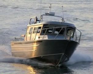
OR another one, custom built/ home made Rick Whelin design, fishit all summer 50 miles offshore average 10 hour days trolling, averaged 70 gallon fuel burn, average cruise between 24 and 28 knots WOT 46 knots stayed out and fished when most didnt, hull performs incredible and turns like a race car.
- Attachments
-
- 1000000581.jpg (64.58 KiB) Viewed 16485 times
-
- 1000000580.jpg (59.46 KiB) Viewed 16485 times
-
kmorin
- Donator 08, 09, 10, 11, 12, 13, 14, 15, 16, 17, 18, 19, 20, 21, 22, 23, 24
- Posts: 1743
- Joined: Mon Aug 18, 2008 1:37 am
- 15
- Location: Kenai, Alaska
Comparing Hulls:Movement Names- Pitch
I'm modeling a very simple shape flat bottom skiff so there are fewer lines on screen and the shape is easier to illustrate.
here the skiff is bow on to a wave and therefore the bow pitches up and down. Pitch is the name for the rotation of boat's waterplane on a transverse 'axel', I show a play ground 'teeter totter'. The boat may be moving forward but I'm trying to isolate the one movement- bow up or down.

near foreground the skiff is level in flat water, next to the right the swell has lifted the bow and behind that the swell is lifting the stern.

slightly different view point to show the pitch of the hull more clearly from close to water level, the movement named Pitch is a tilting of the (AT REST) water plane up or down in Profile View.
I've left the water planes inside the hulls to show the increase in volume forward and then aft as the swell passes along our anchored/un-powered skiff.

the water volume forward to the right is shown as the intersection of the wave along the inside of the hull, and then to the left that same swell passes aft and the increase in volume is moved aft.
Therefore the Center of Buoyancy moves (first) forward to push up and unbalance the hull with an upward pitch by the bow, then shifts aft as the increased volume of displacement moves with the swell behind the original at rest (balanced) CB.
so the CB moves along with the wave's crest/peak and the bow first goes up then the stern goes up, and this motion is called Pitch.

Looking from below the waterline, the same change in displaced volume is obvious, and the movement this causes in the floating hull is also obvious as well.
Pitch is the term used to describe motion around the original center of the waterplane's transverse axis. This motion is not seen or experienced all by itself, as the boat is also rolling or yawing too, (as well as heaving and swaying while it's surging.)
Next we'll roll and yaw a bit.
Cheers,
Kevin Morin
here the skiff is bow on to a wave and therefore the bow pitches up and down. Pitch is the name for the rotation of boat's waterplane on a transverse 'axel', I show a play ground 'teeter totter'. The boat may be moving forward but I'm trying to isolate the one movement- bow up or down.
near foreground the skiff is level in flat water, next to the right the swell has lifted the bow and behind that the swell is lifting the stern.
slightly different view point to show the pitch of the hull more clearly from close to water level, the movement named Pitch is a tilting of the (AT REST) water plane up or down in Profile View.
I've left the water planes inside the hulls to show the increase in volume forward and then aft as the swell passes along our anchored/un-powered skiff.
the water volume forward to the right is shown as the intersection of the wave along the inside of the hull, and then to the left that same swell passes aft and the increase in volume is moved aft.
Therefore the Center of Buoyancy moves (first) forward to push up and unbalance the hull with an upward pitch by the bow, then shifts aft as the increased volume of displacement moves with the swell behind the original at rest (balanced) CB.
so the CB moves along with the wave's crest/peak and the bow first goes up then the stern goes up, and this motion is called Pitch.
Looking from below the waterline, the same change in displaced volume is obvious, and the movement this causes in the floating hull is also obvious as well.
Pitch is the term used to describe motion around the original center of the waterplane's transverse axis. This motion is not seen or experienced all by itself, as the boat is also rolling or yawing too, (as well as heaving and swaying while it's surging.)
Next we'll roll and yaw a bit.
Cheers,
Kevin Morin
kmorin
-
kmorin
- Donator 08, 09, 10, 11, 12, 13, 14, 15, 16, 17, 18, 19, 20, 21, 22, 23, 24
- Posts: 1743
- Joined: Mon Aug 18, 2008 1:37 am
- 15
- Location: Kenai, Alaska
Comparing Hulls: Yaw and Roll
Here are the other two axis of motion around axises through the boat hull/waterplane in Plan View called Yaw. In Body Plan View the rotational motion is called Roll.

Yaw is the boat rotating around a center point like it was a model on a pivot pin stuck down the mast or smoke stack of days gone by. Here there's a ship's wheel to show the directional idea of this rotational movement. The heading of the boat changes by yawing around to port or starboard.
Yes, Yaw rarely happens without movements in the other axis, but we're just isolating that movement again so we all have the same terminology to discuss shapes' movement influences.

From the stern, Yaw to either side is usually the result of helm movement, but waves by the bow or stern can cause Yaw too.

Roll is shown as a big tire that could roll either way, and the skiff shapes are shown on a small swell moving under three hulls. On the right the hull is leaning down into the rising swell until the buoyancy is increased enough to lift the hull (heave) but in the mean time the hull has "rolled down by the port chine". Then the center hull is level as it's waterplane is equal on both sides of the keel plane. The left hand hull is rolled down because the incoming swell (right to left) has lifted the left side before passing away left. The hull rolls down outboard to starboard until the buoyancy is increased enough to equalize the port side's lift and then the hull will settle back to even as the swell passes.

another view to show the swell closer to water level.

and from a higher angle to show the waterlines (inside) of the hulls in the shifts of CB ;transversely.
In the first movement Pitch we saw the CB 'move' or shift fore and aft as the hull was swept by a passing swell bow to stern, and here we see a swell shifting the CB laterally or side to side and the swell moves at 90 deg.s to the keel plane.
I have not taken time to draw all the other combinations of CB shifts. But we can say a quartering sea by the bow OR the stern would shift the CB at diagonals between the axis of the keel and the axis of the amidships frame. The CB shifts are the result of wave surface flowing past the hull and increasing or decreasing the amount of lift/buoyancy in any section of the hull. The shift may be directly along the keel if the boat is aligned directly with waves by the bow, (all Pitch) or at 90 deg.s if if the waves' faces are exactly parallel to the keel (all Roll) but almost always we'll experience some small variation of direction of the wave to the keel plane.
So when we talk about hull movements we need to describe rotations around these three axis, in order to make sure we don't make an already potentially complex discussion - totally incomprehensible.
these are just the three rotational forces in each of the three (X,Y, Z) axises in 3D movement. We also have movement of the whole boat up, Heave: movement of the whole boat straight to the port or starboard or side to side; Sway: and movement of the whole boat straight ahead, or in reverse; Surge.
Cheers,
Kevin Morin
Yaw is the boat rotating around a center point like it was a model on a pivot pin stuck down the mast or smoke stack of days gone by. Here there's a ship's wheel to show the directional idea of this rotational movement. The heading of the boat changes by yawing around to port or starboard.
Yes, Yaw rarely happens without movements in the other axis, but we're just isolating that movement again so we all have the same terminology to discuss shapes' movement influences.
From the stern, Yaw to either side is usually the result of helm movement, but waves by the bow or stern can cause Yaw too.
Roll is shown as a big tire that could roll either way, and the skiff shapes are shown on a small swell moving under three hulls. On the right the hull is leaning down into the rising swell until the buoyancy is increased enough to lift the hull (heave) but in the mean time the hull has "rolled down by the port chine". Then the center hull is level as it's waterplane is equal on both sides of the keel plane. The left hand hull is rolled down because the incoming swell (right to left) has lifted the left side before passing away left. The hull rolls down outboard to starboard until the buoyancy is increased enough to equalize the port side's lift and then the hull will settle back to even as the swell passes.
another view to show the swell closer to water level.
and from a higher angle to show the waterlines (inside) of the hulls in the shifts of CB ;transversely.
In the first movement Pitch we saw the CB 'move' or shift fore and aft as the hull was swept by a passing swell bow to stern, and here we see a swell shifting the CB laterally or side to side and the swell moves at 90 deg.s to the keel plane.
I have not taken time to draw all the other combinations of CB shifts. But we can say a quartering sea by the bow OR the stern would shift the CB at diagonals between the axis of the keel and the axis of the amidships frame. The CB shifts are the result of wave surface flowing past the hull and increasing or decreasing the amount of lift/buoyancy in any section of the hull. The shift may be directly along the keel if the boat is aligned directly with waves by the bow, (all Pitch) or at 90 deg.s if if the waves' faces are exactly parallel to the keel (all Roll) but almost always we'll experience some small variation of direction of the wave to the keel plane.
So when we talk about hull movements we need to describe rotations around these three axis, in order to make sure we don't make an already potentially complex discussion - totally incomprehensible.
these are just the three rotational forces in each of the three (X,Y, Z) axises in 3D movement. We also have movement of the whole boat up, Heave: movement of the whole boat straight to the port or starboard or side to side; Sway: and movement of the whole boat straight ahead, or in reverse; Surge.
Cheers,
Kevin Morin
kmorin
-
kmorin
- Donator 08, 09, 10, 11, 12, 13, 14, 15, 16, 17, 18, 19, 20, 21, 22, 23, 24
- Posts: 1743
- Joined: Mon Aug 18, 2008 1:37 am
- 15
- Location: Kenai, Alaska
Comparing Hulls: XYZ MOTIONS
Just above we looked at pitch, roll and yaw or rotational movement around the XYZ axises through the hull/waterplane and here we look at the entire boat moving in those directions. Admittedly, terms not commonly used today, but that's mainly because the discussion(s) are not very exact and I'm trying to move toward a clear -not vague- discussion of shape vs motion for welded hulls in this topic.

X axis is the line down the keel, so Surge is forward motion, Y axis is transverse amidships, and side to side motion is Sway, and the Z axis is up (and down) and this motion is Heave.
From these definitions and sketches we could begin to discuss motion of a hull. For example, if a hull is moving into a wave at a slow speed ahead, (surge/ing) then the Pitch by the bow is accompanied by Heave as the wave crest moves along the waterline.
The entire boat IS lifted, by the wave, just as the bow IS tilted upward as the swell initially creates more buoyancy in the forward half of the hull therefore moving the CB forward of the CG and raising the bow. So both Pitch and Heave happen in relation to one another.
If the boat were moving at 45 degrees to oncoming seas (quartering seas by the bow) then the entire hull may experience Sway to the leeward as the seas imparted some sideways motion due to their angle on the bow.
Likewise, a similar series of combined motions can be used to describe a hull's behavior in any axis of motion.
Therefore, if a hull is moving ahead of a following sea (seas overtaking the hull from astern) then it Surges down the wave faces and is Pitched down by the bow, as the wave overtakes intitally lifting the stern. If close attention is not paid to Yaw (steerage/heading) the bow may Yaw sharply to one side. If allowed to Yaw, the forces of buoyancy aft, combined with increasing Pitch down by the bow, may immerse the bow topsides so deeply the forces of suddenly added buoyancy will add to the Yaw forces and the boat may begin to Roll to its lee side, as the hull Yaws sideways/broach to the wave.
When these conditions continue, the Yawing motion turns the keel at right angles to the sea's crest, and the CB moves radically upward away from the trough side (lee side) of the hull and the Roll forces may over turn the boat. If the CB moved sufficiently up the hull toward the wave crest, while the keel was parallel to the wave; the CG may be so far out of balance (not under the CB or even close) that it acts to Roll the hull over.
We haven't talked about drag(s) or thrust yet, so I'm leaving forces out, but this set of movements, described by name, can make the description of hull movement clear enough for everyone to discuss the 'same things'. (but) Without these terms we'll find ourselves talking about movements and hull actions using terms that don't mean the same thing to each of us.
cheers,
Kevin Morin
kmorin
-
kmorin
- Donator 08, 09, 10, 11, 12, 13, 14, 15, 16, 17, 18, 19, 20, 21, 22, 23, 24
- Posts: 1743
- Joined: Mon Aug 18, 2008 1:37 am
- 15
- Location: Kenai, Alaska
Comparing Hulls: Momentum
We need to begin including more forces in this shape/movement discussion, we've already discussed the force lifting a boat is buoyancy and we need to add a few more. Momentum is the force equal to the speed times the weight (mass times velocity) and the heavier the weight, once it's moving at an equal speed, the more the momentum.
Images for our purposes are symbolic, again, to show the idea while skipping lots of details so we can focus on boats' shape behavior.

In our imagination we have a 'swing set' with a fillet knife on one swing chain and an axe on the other swing chain, both held above our waves on big swing set, since these waves are 3' tall!

Let both cutting tools loose and they swing downward to the oncoming waves, sort of like two boats, where one is larger and heavier than the other, but the lighter 'boat' is sharper, thinner, and overall smaller.

Both 'leading edges' or 'bows of the boats' hit the wave face with unrealistically sharp edges. They both begin to part the water, and each one's displacement begins to increase as they are further immersed into the wave face. However, they don't weigh the same so their momentum is not the same, so the force of the fall converted to moving through the wave is not the same.

Because the lighter fillet knife has so much less momentum (same speed, less weight= lower momentum) it will be stopped by the resistance of the buoyancy combined with drag which are more than the momentum of that light weight moving at the same speed as the axe. The axe continues its swing, slowed by drag and buoyancy but the higher weight allows the falling/swinging axe -even though it is wider and more bulky a shape - to plow on through the wave.
What does this remind us to consider? Not only is hull shape comparison important in this discussion, one very MAJOR factor is hull displacement. If two boats are the same exact hull shape, but one is loaded more heavily than the other, and they are traveling at the same speed, the heavier hull's increased momentum will help to 'keep going' or:
to have less pitch for the same immersion in a wave
to have more surge due to increased momentum
to have less roll because the (lowered hull) raised waterlines provide more resistance to roll
to 'ride smoother' than the lighter displacement boat
to have less 'slam' or rapid deceleration because the increased momentum resists slowing as rapidly as the lighter boat.
So, shape is a big contribution to how the boat will perform but its not the entire 'story'. Ride or comfort is also a factor of displacement at any speed since there will also need to be a COMPARISON of momentum when comparing hulls' performance.

A very deep V, sharp entry bottom in a boat that is less than half the displacement of a less deeply shaped hull; will not necessarily be the smoother riding boat. Shape, sea state and momentum (especially as related to displacement) all contribute in the performance of a hull; its not exclusively hull form.
cheers,
Kevin Morin
Images for our purposes are symbolic, again, to show the idea while skipping lots of details so we can focus on boats' shape behavior.
In our imagination we have a 'swing set' with a fillet knife on one swing chain and an axe on the other swing chain, both held above our waves on big swing set, since these waves are 3' tall!
Let both cutting tools loose and they swing downward to the oncoming waves, sort of like two boats, where one is larger and heavier than the other, but the lighter 'boat' is sharper, thinner, and overall smaller.
Both 'leading edges' or 'bows of the boats' hit the wave face with unrealistically sharp edges. They both begin to part the water, and each one's displacement begins to increase as they are further immersed into the wave face. However, they don't weigh the same so their momentum is not the same, so the force of the fall converted to moving through the wave is not the same.
Because the lighter fillet knife has so much less momentum (same speed, less weight= lower momentum) it will be stopped by the resistance of the buoyancy combined with drag which are more than the momentum of that light weight moving at the same speed as the axe. The axe continues its swing, slowed by drag and buoyancy but the higher weight allows the falling/swinging axe -even though it is wider and more bulky a shape - to plow on through the wave.
What does this remind us to consider? Not only is hull shape comparison important in this discussion, one very MAJOR factor is hull displacement. If two boats are the same exact hull shape, but one is loaded more heavily than the other, and they are traveling at the same speed, the heavier hull's increased momentum will help to 'keep going' or:
to have less pitch for the same immersion in a wave
to have more surge due to increased momentum
to have less roll because the (lowered hull) raised waterlines provide more resistance to roll
to 'ride smoother' than the lighter displacement boat
to have less 'slam' or rapid deceleration because the increased momentum resists slowing as rapidly as the lighter boat.
So, shape is a big contribution to how the boat will perform but its not the entire 'story'. Ride or comfort is also a factor of displacement at any speed since there will also need to be a COMPARISON of momentum when comparing hulls' performance.
A very deep V, sharp entry bottom in a boat that is less than half the displacement of a less deeply shaped hull; will not necessarily be the smoother riding boat. Shape, sea state and momentum (especially as related to displacement) all contribute in the performance of a hull; its not exclusively hull form.
cheers,
Kevin Morin
kmorin
-
mojomizer
- Contributor/Donator '08
- Posts: 1205
- Joined: Sat Jan 12, 2008 4:38 pm
- 16
- Location: Orange County
Re: Comparing Hulls
I am really enjoying your explanations and illustrations Kevin. Thank you.
Mark
2325 WA PACIFICSKIFF
2325 WA PACIFICSKIFF
Re: Comparing Hulls
I agree. Kevin must really have a hard time when people quote their transom deadrise as they reason their boat is the best in rough seas. It is almost like we should be paying him for a class here or something.
Jim
-
dawgaholic
- Posts: 509
- Joined: Thu Oct 06, 2011 9:20 am
- 12
Re: Comparing Hulls
For real....unless you do teach, you may have missed your calling Kevin for you do it very well!jrogers wrote:I agree. Kevin must really have a hard time when people quote their transom deadrise as they reason their boat is the best in rough seas. It is almost like we should be paying him for a class here or something.
KM's sharing has provided this landlubber with a fundamental understanding of boat construction and behavior which has elevated me above my previous clueless existence. And just like a great Professor, the progression of his presentation lets you experience that little light bulb going off in your head.
Thank you very much Kevin.
I only do what the voices in the Tackle Box tell me to.
-
kmorin
- Donator 08, 09, 10, 11, 12, 13, 14, 15, 16, 17, 18, 19, 20, 21, 22, 23, 24
- Posts: 1743
- Joined: Mon Aug 18, 2008 1:37 am
- 15
- Location: Kenai, Alaska
Re: Comparing Hulls: What a Drag!
gentlemen, thanks for the encouraging words, but let's talk about a 'drag' on boats.
I'm more than willing to have some other definitions added here, and especially since I'm
essentially giving rules of thumb for boat performance based on very broad approximations
of the forces at work when the hull moves through the water. I may be distorting a better understanding
of the physics at work, so anyone with remarks about these approximations should post up!
I'm making some pretty broad summaries of the physics involved so we don't have deep into
those terms, equations and leave our conversational type of discussion. The good part of that
is we can get general ideas without spending time with too much math but the down side is
I can get too inexact or too vague and give readers false impressions.
So, if you see a way to make these points more effectively, more clearly and more exactly:
PLEASE let us hear from you!
Before we can really get to a full set of boat hull shapes in the waves illustrations (assuming I am able
to make an illustration of these effects at work?) we need to keep adding more basics to the discussion.
Drag is the force 'slowing us down' as in "What a Drag.." a saying from days gone bye.
That is; resistance to moving forward in (and on) the water is Drag. Drag
comes in two main types on boats, then it divides again, into sub-types, so we'll take the 'bigger' scale forces
to refer back too when we start to talk about actual hulls' performance comparisons.
Air drag (resistance to moving in air) is the force resisting the boat that causes your gas mileage when you're towing.
When you drive without the boat behind the truck you get 10-20-30(?) miles per gallon but when you pull your boat,
figure of mpg goes way down.
Further, if you have an open jonboat that has no weather helm or even a console, the gas mileage is MORE
than if you put a duck blind on that jonboat before towing to the launch.
The frontal area and the shape of the Body Plan view of your boat effects the mileage. So if you're traveling on the
water at highway speeds, there is some wind resistance so that a lower Profile View/Body Plan view, smaller cross
section boat will increase the truck-only mileage LESS than a bigger boat with a bigger cabin and frontal area.
There is air Drag or resistance to moving the boat's frontal outline through the air- one type of Drag.
But... water is much more dense than air (hundreds of times denser) so the other main Drag is from water but
these forces are hundreds of times more than the air drag or resistance. Here, we divide water Drag into
two main types and ignore some others- on purpose.
First, a shape (or a form) moving through water has Drag based on the shape. If Mojo puts his hand in the grandkid's wading pool like a Karate chop, on edge, it will be fairly easy to pull his hand through the water as the shape is sort of
streamlined. But what if Mojomizer rolls his hand at the wrist 90 degrees and drags it the same path with palm to the
water?
Then not only is it much harder to pull his hand- the harder he pulls the harder it is to pull.
We all know the resistance is much greater the less streamlined the object moving through the water. Therefore
we'll call this Shape or Form drag, and we'll all agree that experience tells us the jon boat's bow has more form drag
than a Pacific Skiff's bow, and the Cigarette (tm) Boat (bikini freighter) has less form resistance than the Pacific.

Here is our axe from earlier images, moving toward the screen along with another axe upside down. To the right, the blade parts the water with a very narrow angle or 'sharp entry' but the handle parts the water as a 'circle' or round cylinder.
The angle that water is parted contributes to the amount of Drag on the object. So Shape Drag (or Form Drag) comes from the angle the water is parted and the remaining shape of the object. We know that plowing an overloaded jon boat through the water is harder than pushing a narrow canoe with only person in it. The Shape Drag of one is broad and flat while the other is narrow and sharp; the smaller the angle of entry the less resistance in Shape Drag.

To improve our visualization of the Shape Drag resistance most text books show some imaginary lines around the object. These 'flow' lines are shown here so we can see their original angle contributes to how these lines 'flow' or 'move' around the object.
Its important that we agree these lines are shown for illustration, as they can only be shown in wind tunnels, flow channels and other experimental set ups. I advise you to go to http://en.wikipedia.org/wiki/Drag_coefficient or some other detailed article if you're interested in 'the rest of the story' since I'm making some big approximations here.

this image shows the actual object, then to the right some 'waterline' tracings with a few example flow lines, then to the right most a pair of rectangles with example flow lines.
All these images are intended to confirm the ideas about drag related to the various shapes of objects.
Next; we need to agree that surface is related to drag too; Drag in water comes from not only how the object is shaped
but how much surface is wetted when the object moves though the water.
If one of the grand kids pulls their hand through the pool the child's hand being smaller than mojomizer's will have less surface area - in the same position of movement. The overall surface area reduction means there's a Drag reduction; the more area of an object coated with water, the more Drag on that object due to 'wetted area drag'.
Not only is the shape of the boat important in considering resistance, so is the amount of the boat that is 'dragging' water along with the weight/displacement of the hull.
And to make things even a little bit more complicated, after we add Drag's two main contributions; water gets harder if you enter/impact/hit it fast(er) and water is softer if you don't hit it as hard! When water's 'hard' a boat can 'bounce'- about like a rock skipping- but if water is impacted in the 'soft' state you don't get any 'bounce' from water's hardness.
This all comes together in a planning hull as it runs.
Cheers,
Kevin Morin
I'm more than willing to have some other definitions added here, and especially since I'm
essentially giving rules of thumb for boat performance based on very broad approximations
of the forces at work when the hull moves through the water. I may be distorting a better understanding
of the physics at work, so anyone with remarks about these approximations should post up!
I'm making some pretty broad summaries of the physics involved so we don't have deep into
those terms, equations and leave our conversational type of discussion. The good part of that
is we can get general ideas without spending time with too much math but the down side is
I can get too inexact or too vague and give readers false impressions.
So, if you see a way to make these points more effectively, more clearly and more exactly:
PLEASE let us hear from you!
Before we can really get to a full set of boat hull shapes in the waves illustrations (assuming I am able
to make an illustration of these effects at work?) we need to keep adding more basics to the discussion.
Drag is the force 'slowing us down' as in "What a Drag.." a saying from days gone bye.
That is; resistance to moving forward in (and on) the water is Drag. Drag
comes in two main types on boats, then it divides again, into sub-types, so we'll take the 'bigger' scale forces
to refer back too when we start to talk about actual hulls' performance comparisons.
Air drag (resistance to moving in air) is the force resisting the boat that causes your gas mileage when you're towing.
When you drive without the boat behind the truck you get 10-20-30(?) miles per gallon but when you pull your boat,
figure of mpg goes way down.
Further, if you have an open jonboat that has no weather helm or even a console, the gas mileage is MORE
than if you put a duck blind on that jonboat before towing to the launch.
The frontal area and the shape of the Body Plan view of your boat effects the mileage. So if you're traveling on the
water at highway speeds, there is some wind resistance so that a lower Profile View/Body Plan view, smaller cross
section boat will increase the truck-only mileage LESS than a bigger boat with a bigger cabin and frontal area.
There is air Drag or resistance to moving the boat's frontal outline through the air- one type of Drag.
But... water is much more dense than air (hundreds of times denser) so the other main Drag is from water but
these forces are hundreds of times more than the air drag or resistance. Here, we divide water Drag into
two main types and ignore some others- on purpose.
First, a shape (or a form) moving through water has Drag based on the shape. If Mojo puts his hand in the grandkid's wading pool like a Karate chop, on edge, it will be fairly easy to pull his hand through the water as the shape is sort of
streamlined. But what if Mojomizer rolls his hand at the wrist 90 degrees and drags it the same path with palm to the
water?
Then not only is it much harder to pull his hand- the harder he pulls the harder it is to pull.
We all know the resistance is much greater the less streamlined the object moving through the water. Therefore
we'll call this Shape or Form drag, and we'll all agree that experience tells us the jon boat's bow has more form drag
than a Pacific Skiff's bow, and the Cigarette (tm) Boat (bikini freighter) has less form resistance than the Pacific.
Here is our axe from earlier images, moving toward the screen along with another axe upside down. To the right, the blade parts the water with a very narrow angle or 'sharp entry' but the handle parts the water as a 'circle' or round cylinder.
The angle that water is parted contributes to the amount of Drag on the object. So Shape Drag (or Form Drag) comes from the angle the water is parted and the remaining shape of the object. We know that plowing an overloaded jon boat through the water is harder than pushing a narrow canoe with only person in it. The Shape Drag of one is broad and flat while the other is narrow and sharp; the smaller the angle of entry the less resistance in Shape Drag.
To improve our visualization of the Shape Drag resistance most text books show some imaginary lines around the object. These 'flow' lines are shown here so we can see their original angle contributes to how these lines 'flow' or 'move' around the object.
Its important that we agree these lines are shown for illustration, as they can only be shown in wind tunnels, flow channels and other experimental set ups. I advise you to go to http://en.wikipedia.org/wiki/Drag_coefficient or some other detailed article if you're interested in 'the rest of the story' since I'm making some big approximations here.
this image shows the actual object, then to the right some 'waterline' tracings with a few example flow lines, then to the right most a pair of rectangles with example flow lines.
All these images are intended to confirm the ideas about drag related to the various shapes of objects.
Next; we need to agree that surface is related to drag too; Drag in water comes from not only how the object is shaped
but how much surface is wetted when the object moves though the water.
If one of the grand kids pulls their hand through the pool the child's hand being smaller than mojomizer's will have less surface area - in the same position of movement. The overall surface area reduction means there's a Drag reduction; the more area of an object coated with water, the more Drag on that object due to 'wetted area drag'.
Not only is the shape of the boat important in considering resistance, so is the amount of the boat that is 'dragging' water along with the weight/displacement of the hull.
And to make things even a little bit more complicated, after we add Drag's two main contributions; water gets harder if you enter/impact/hit it fast(er) and water is softer if you don't hit it as hard! When water's 'hard' a boat can 'bounce'- about like a rock skipping- but if water is impacted in the 'soft' state you don't get any 'bounce' from water's hardness.
This all comes together in a planning hull as it runs.
Cheers,
Kevin Morin
kmorin
-
kmorin
- Donator 08, 09, 10, 11, 12, 13, 14, 15, 16, 17, 18, 19, 20, 21, 22, 23, 24
- Posts: 1743
- Joined: Mon Aug 18, 2008 1:37 am
- 15
- Location: Kenai, Alaska
Comparing Hulls: more Drag
I admit that its a drag to discuss, Drag, but we'll do it some more here. I'm hoping the images will help make a point, I'm trying to avoid getting too deep into physics and stay with rules of thumb, so if this isn't working, I won't know that unless you post a reply.
If you Drag a chain, you've probably noticed; it gets harder to do the farther you go?" If you move the end of chain and only pull a few links, then the drag you pull is equal to the first full link, the some of the next link and a lesser amount of the third and so forth? But if you end up pulling the entire chain or lifting it, then you'll find the weight gradually increases by the number of links you pull.
Wetted Surface Drag in water can be viewed almost like moving a chain.

Here is a tiny key chain made of the small round hollow metal links and the small rods in between to link the chain. This one floats and it represents a series of water molecules 'chained' together.

Close up view shows the hollow balls and the rod links, and for our illustration the balls are molecules and the links are 'bonds' that hold them together; in the case of water, not very strong 'links' or bonds. Buttttttt.... and as you know there's always a but.... nothing is for free in the water.... but the links can be broken pretty easily.
[We already discussed briefly and we'll come back to the force needed to break these links; these links break or part the easiest when that is done slowly. If the links are broken rapidly they are MUCH HARDER to break than if they are broken slowly.]
When the links break the water is still 'sticky' and will adhere, or stick to the surface that is passed through the water.
So if our chain is broken in the illustration, the links will 'stick' to some degree to the object breaking the bond or 'link'.

Here are a couple of chains being broken by a translucent bow of a boat. The chain links parted and the sticky broken link tries to 'stay with' the hull surface. Water is 'sticky' when we break the bonds, especially if we break them slowly. Some of the chains not 'hit' by the hull are bending, due to the movement of the one 'chain' that has been hit.

As the bow of our boat moves along it breaks the chains across the course of the boat and the links stick to the hull and begin to travel WITH the hull as it moves. But the water farther away from the hull 'stays' where it was- since the only 'link' to the water near the hull is being ABSORBED by the gradual shift of the links in between.

I've painted the hull gray instead of 'glass' colored in case the image just before was confusing? Still the chain links or molecules along the hull's surface which is in contact (with these water molecules) are sticking to the hull ; SO!!!! more and more of each "chain of water" is being 'pulled' or lifted or carried by the hull. We can see this by the increased number of 'links' that are rotated and moved along the boat's course; compared to their original location.

This image shows the hull's bow is about to be farther along the course and when that happens the chain of molecules, shown by our key chain balls and links, has moved farther still. The boat is literally 'dragging' water along with it. (What is this resistive force called? DRAG)

This is the follow-on image showing the hull's bow moved, down course, and the chain has moved even further due to the 'sticky' broken links being attached to the hull; temporarily. So the farther along the molecules in the chain are moved the more 'weight of the chain' is Drag(ged) along by the boat.

Last image for this concept shows a series of our key chain/water molecules having moved some distance from where they were when the boat split the chain and the sticky beads moved with the hull. The boat had to Drag/pull/move along this 'wall of water' which weighed what water does per cubic foot- and there was some force required to 'break the chain(s)' too.
So "Dragging a chain of water molecules" is a force slowing the boats forward movement.
Wetted Surface Drag or skin friction is that part of Drag (force) that results from Dragging water with the boat. Water is sticky, in some instances but less so in others, so part of the forces resisting our engine's thrust and hull movement is Wetted Surface Drag.
I spent a few minutes trying to find a good mental image here so if anyone can think of a better set of images for resistive drag or skin friction, I'd be happy to edit this post to show more effective images.
Believe it or not, (??) at some point we're going to try to relate all these images and ideas into a discussion of boat performance due to hull shape. Next we need to deal with 'hard water'.
Cheers,
Kevin Morin
If you Drag a chain, you've probably noticed; it gets harder to do the farther you go?" If you move the end of chain and only pull a few links, then the drag you pull is equal to the first full link, the some of the next link and a lesser amount of the third and so forth? But if you end up pulling the entire chain or lifting it, then you'll find the weight gradually increases by the number of links you pull.
Wetted Surface Drag in water can be viewed almost like moving a chain.
Here is a tiny key chain made of the small round hollow metal links and the small rods in between to link the chain. This one floats and it represents a series of water molecules 'chained' together.
Close up view shows the hollow balls and the rod links, and for our illustration the balls are molecules and the links are 'bonds' that hold them together; in the case of water, not very strong 'links' or bonds. Buttttttt.... and as you know there's always a but.... nothing is for free in the water.... but the links can be broken pretty easily.
[We already discussed briefly and we'll come back to the force needed to break these links; these links break or part the easiest when that is done slowly. If the links are broken rapidly they are MUCH HARDER to break than if they are broken slowly.]
When the links break the water is still 'sticky' and will adhere, or stick to the surface that is passed through the water.
So if our chain is broken in the illustration, the links will 'stick' to some degree to the object breaking the bond or 'link'.
Here are a couple of chains being broken by a translucent bow of a boat. The chain links parted and the sticky broken link tries to 'stay with' the hull surface. Water is 'sticky' when we break the bonds, especially if we break them slowly. Some of the chains not 'hit' by the hull are bending, due to the movement of the one 'chain' that has been hit.
As the bow of our boat moves along it breaks the chains across the course of the boat and the links stick to the hull and begin to travel WITH the hull as it moves. But the water farther away from the hull 'stays' where it was- since the only 'link' to the water near the hull is being ABSORBED by the gradual shift of the links in between.
I've painted the hull gray instead of 'glass' colored in case the image just before was confusing? Still the chain links or molecules along the hull's surface which is in contact (with these water molecules) are sticking to the hull ; SO!!!! more and more of each "chain of water" is being 'pulled' or lifted or carried by the hull. We can see this by the increased number of 'links' that are rotated and moved along the boat's course; compared to their original location.
This image shows the hull's bow is about to be farther along the course and when that happens the chain of molecules, shown by our key chain balls and links, has moved farther still. The boat is literally 'dragging' water along with it. (What is this resistive force called? DRAG)
This is the follow-on image showing the hull's bow moved, down course, and the chain has moved even further due to the 'sticky' broken links being attached to the hull; temporarily. So the farther along the molecules in the chain are moved the more 'weight of the chain' is Drag(ged) along by the boat.
Last image for this concept shows a series of our key chain/water molecules having moved some distance from where they were when the boat split the chain and the sticky beads moved with the hull. The boat had to Drag/pull/move along this 'wall of water' which weighed what water does per cubic foot- and there was some force required to 'break the chain(s)' too.
So "Dragging a chain of water molecules" is a force slowing the boats forward movement.
Wetted Surface Drag or skin friction is that part of Drag (force) that results from Dragging water with the boat. Water is sticky, in some instances but less so in others, so part of the forces resisting our engine's thrust and hull movement is Wetted Surface Drag.
I spent a few minutes trying to find a good mental image here so if anyone can think of a better set of images for resistive drag or skin friction, I'd be happy to edit this post to show more effective images.
Believe it or not, (??) at some point we're going to try to relate all these images and ideas into a discussion of boat performance due to hull shape. Next we need to deal with 'hard water'.
Cheers,
Kevin Morin
kmorin
-
mojomizer
- Contributor/Donator '08
- Posts: 1205
- Joined: Sat Jan 12, 2008 4:38 pm
- 16
- Location: Orange County
Re: Comparing Hulls
Great Googly Moogly Holy Moly..............Eulerian and langrangian concepts, Savitsky, Brownian Motion, WaterSkiers Paradox, S F Hoerner Fluid-dynamic drag. Has my limited head spinning. I do like S F Hoerner though and will read his writing, sitting on the "Thinkers Throne" reading and re-reading and looking up concepts and formula's till I get it. Pages 189 and Pages 207 particularly.
This You Tube video has me flashing back to Grade School. Three of those deep fried greasy burritos and after lunch science class...... face down drooling sleep. At over 50, now it makes me think and captures the imagination. I do find myself dreaming of happy hour (Nap time.) though.
http://www.youtube.com/watch?v=DOUfyDHxkYQ
We at AAB are so fortunate that you Kevin, are here to explain the workings of boat hulls without murking the waters of what I think is a complex subject. Boat hulls of verying size, design and weight in a dynamic enviroment of the oceans and seas.............is Extraordinary and Hurculean in effort Again........ Thank You.
This You Tube video has me flashing back to Grade School. Three of those deep fried greasy burritos and after lunch science class...... face down drooling sleep. At over 50, now it makes me think and captures the imagination. I do find myself dreaming of happy hour (Nap time.) though.
http://www.youtube.com/watch?v=DOUfyDHxkYQ
We at AAB are so fortunate that you Kevin, are here to explain the workings of boat hulls without murking the waters of what I think is a complex subject. Boat hulls of verying size, design and weight in a dynamic enviroment of the oceans and seas.............is Extraordinary and Hurculean in effort
Mark
2325 WA PACIFICSKIFF
2325 WA PACIFICSKIFF
Re: Comparing Hulls
Kevin, your swinging axe metaphor brings to mind a Winninghoff hull I have a few pictures of. I know its ugly and its a displacement but what works with this boat and what fails?
- bow-on.jpg (51.9 KiB) Viewed 15141 times
- stbd qtr.jpg (61.03 KiB) Viewed 15141 times
- stbd beam.jpg (63.58 KiB) Viewed 15141 times
1987 24' LaConner pilothouse workboat, 225 Suzuki

please view and like: https://www.facebook.com/bottompainting/
please view and like: https://www.facebook.com/bottompainting/
-
kmorin
- Donator 08, 09, 10, 11, 12, 13, 14, 15, 16, 17, 18, 19, 20, 21, 22, 23, 24
- Posts: 1743
- Joined: Mon Aug 18, 2008 1:37 am
- 15
- Location: Kenai, Alaska
Re: Comparing Hulls
sorry to be late in continuing this topic, work had become more involved and taken up more time.
The Winninghoff shown, traveling at relatively low speed would 'cut' the waves well, then the abrupt transition to the more full shape would change the waterplane area and therefore buoyancy in the bow, in very short vertical distance. So the water moving up the stem and bow due to the sharp shape and the momentum of the boat behind it, driving it through the waves, would somewhat rapidly change directions with lots of lift by the bow.
Water that was traveling upward would be traveling more outward from the keel when it reached the rising and very wide chine.
So the boat would lift over the tops of (taller) waves but run right through (axe example) anything shorter than the bow's huge reverse chine. The angle of the hull (Body Plan) displacement change would not only lift the bow due to the buoyancy it provided but the shape of the lower surface would vector or direct the water away from the hull, drying out the bow and throwing spray away from the boat.
I'd say she was intended to run into 3-5' head seas at hull speed, maybe 10-14 mph?, She may have a planing hull (?) it depends on her power, but she'd run without much impact due to the exaggerated forefoot, and I'd say the waves were not open ocean swells four or five boat lengths apart but closer, a choppy seas with sharper face and back angle like a big bay or inlet somewhere?
If she was/is a commercial boat used for near inshore gear the shape looks like a good idea for running with a load and not burying the bow, this might have been her intended purpose but I'm just guessing looking at the pictures. In a following sea, if she were in waves/swells large enough to bury that bow, she may have been hard to steer but I can't tell what her keel lateral area looks like. If the keel is as exposed below the hull as it seems (?) then even in a following sea that long keel may have kept her heading without slewing? A shot from her transom would help you guess at that handling characteristic, overall the long keel would help keep her head in both a head and following sea.
She looks like a hard chine version of a down east lobster boat, so she may have been built for a specific fishery?
I notice the lines of the hull plates are not very uniform, they waver/wander indicating this must have been a very early Winninghoff? The technique to layout and cut those plates with a fair edge producing a clean curve is not difficult so I'll imply this was a low hull number from the builder? Further, there appear some re-plating and maybe repair plates overlapping the chine line in the Profile picture. This indicates some pretty hard use or some repairs for another reason?
Her rigging has several masts, booms an A frame and a davit, all of that implies commercial gear but not just one type??? Not sure what she's for but I'd guess she's run well, narrow hull at just below planing speeds, and the very sharp forefoot would 'knife' into short waves, with a good load aboard, or a running waterline higher up the stem than the waterline boot.
Cheers,
Kevin Morin
kmorin
-
kmorin
- Donator 08, 09, 10, 11, 12, 13, 14, 15, 16, 17, 18, 19, 20, 21, 22, 23, 24
- Posts: 1743
- Joined: Mon Aug 18, 2008 1:37 am
- 15
- Location: Kenai, Alaska
Comparing Hulls: Hard Water
We've been reviewing the basics about what forces effect a boat's hull motion and therefore performance, but we need more background before we can begin the actual hull model movement comparisons.
To continue; it's time to begin to look more closely at water's "internal chains", and specifically how strong these chains are in different conditions? To do that; we'll skip a rock because that's the best way to show this idea as far as I can figure out? (Please recall that I'm willing to modify these images, and edit the text to give better illustrations and make these concepts more clearly, so PM if you don't want to post or k.morin@kmmail.net direct if you have ideas or questions.)

here is a hand with a 'perfect' skipping stone, a little 'flying saucer' shape that we're going to throw into a long trough of water.

The throw- notice this is ALL the force we're going to get on the rock- a one time tossing force, there is no engine or continuous push one this shape. So ALL the force is given when the rock releases from the hand. This helps us to make the points we're concentrating on in this post.

Here is a picture of the rock coming at a low angle to the water, with the full speed (rate of travel/velocity) of the throw at the left side of the image.
The path it will take is shown on a white back board showing the rock will hit the water and bounce. Each skip or bounce will be closer to the last one than the one before, or they will get shorter and shorter, and also they will all get lower and lower.
Yes, I do realize that skipped rocks probably won't/don't skip as high as I've shown but I'm working for an image here not scale of the path traveled by this 'rock'.

This image shows the path as the upper border of a white to orange area, and to the right the paths are shown lowered and shorter than the previous flight path to the left.
Eventually the rock will slow down and sink, but until that time we learn some facts critical to our discussion.
#1 If a rock (an object) hits/impacts water fast enough; the water's 'chains' are strong enough to bounce a rock!
#2 Each time the rock bounces; it looses some energy into the water in drag and by moving (some) water side ways and breaking chains, plus- the rock collects some water that sticks to the surface adding to its weight without providing any lift or buoyancy.
#3 The shorter and shorter bounces that are lower and lower off the water's surface, end up 'collecting' all the energy or momentum from the rock which eventually slows so much it 'eases' into the water when the water's 'chains' won't hold it up any more.
#4 The weight of the water displaced by the rock is less than the weight of the rock so it will sink if left to float by the sole force of buoyancy.
Next we'll have to look at a single skip point or splash down of the rock.
Cheers,
Kevin Morin
To continue; it's time to begin to look more closely at water's "internal chains", and specifically how strong these chains are in different conditions? To do that; we'll skip a rock because that's the best way to show this idea as far as I can figure out? (Please recall that I'm willing to modify these images, and edit the text to give better illustrations and make these concepts more clearly, so PM if you don't want to post or k.morin@kmmail.net direct if you have ideas or questions.)
here is a hand with a 'perfect' skipping stone, a little 'flying saucer' shape that we're going to throw into a long trough of water.
The throw- notice this is ALL the force we're going to get on the rock- a one time tossing force, there is no engine or continuous push one this shape. So ALL the force is given when the rock releases from the hand. This helps us to make the points we're concentrating on in this post.
Here is a picture of the rock coming at a low angle to the water, with the full speed (rate of travel/velocity) of the throw at the left side of the image.
The path it will take is shown on a white back board showing the rock will hit the water and bounce. Each skip or bounce will be closer to the last one than the one before, or they will get shorter and shorter, and also they will all get lower and lower.
Yes, I do realize that skipped rocks probably won't/don't skip as high as I've shown but I'm working for an image here not scale of the path traveled by this 'rock'.
This image shows the path as the upper border of a white to orange area, and to the right the paths are shown lowered and shorter than the previous flight path to the left.
Eventually the rock will slow down and sink, but until that time we learn some facts critical to our discussion.
#1 If a rock (an object) hits/impacts water fast enough; the water's 'chains' are strong enough to bounce a rock!
#2 Each time the rock bounces; it looses some energy into the water in drag and by moving (some) water side ways and breaking chains, plus- the rock collects some water that sticks to the surface adding to its weight without providing any lift or buoyancy.
#3 The shorter and shorter bounces that are lower and lower off the water's surface, end up 'collecting' all the energy or momentum from the rock which eventually slows so much it 'eases' into the water when the water's 'chains' won't hold it up any more.
#4 The weight of the water displaced by the rock is less than the weight of the rock so it will sink if left to float by the sole force of buoyancy.
Next we'll have to look at a single skip point or splash down of the rock.
Cheers,
Kevin Morin
kmorin
Re: Comparing Hulls
Having read most of the thread, what I'd like to know is this; are you really going to be able to tell the difference of 5 degrees at bow entry and 2 degrees on the deadrise in a 22' boat? All other things being equal?
-
mojomizer
- Contributor/Donator '08
- Posts: 1205
- Joined: Sat Jan 12, 2008 4:38 pm
- 16
- Location: Orange County
Re: Comparing Hulls
Hello JJ225, To me this thread is about the getting a rudimentary understanding of hull designs. How they apply to Varying Oceanic conditions. The ride characteristic preferences that a individual may want or need.
The understanding that there is no perfect or magical design specifications that works for all. All hull designs are a compromise.
I believe that any changes in hull angles does change the characteristics of hull performance. Some may be imperceptible to our senses. As a extreme, take the America's Cup sailing races. I bet that the hull angles are scrutinized and tested trying to get minute advantages in performance. Taking into consideration where the race is taking place and the prevailing conditions at race time. Captain and crew skills are at a premium and are major factor at the winning equation.
I remember as a kid wondering why they hid the bow on those hulls. I remember the first winged keel and the major advantage it had in reducing drag on the displacement hulls.
I like looking at all the different hull designs and one day being able to try and understand the thought process of their designers. To me it is just as interesting to see boat design as art and trying to understand what the artist is trying to convey.
I was just watching the Science Channel and how the Mongol Kubla Khan failed to invade some Islands seems he took his horde out to sea in river boats when a typhoon stuck. He lost his horde. Boat Design, Sea Conditions and poor judgement changed history.
2 Degrees and 5 degrees on a 22 foot Aluminum Alloy Boat may not change history. It does change Froude's equation????
Last edited by mojomizer on Sat Oct 20, 2012 12:33 am, edited 1 time in total.
Mark
2325 WA PACIFICSKIFF
2325 WA PACIFICSKIFF
-
mojomizer
- Contributor/Donator '08
- Posts: 1205
- Joined: Sat Jan 12, 2008 4:38 pm
- 16
- Location: Orange County
Re: Comparing Hulls
Check this out: https://www.navalengineers.org/Proceedi ... th_Lin.pdf
Page 867 (third page down) has an interesting chart and commentary of varying deadrise attributes on subsequent pages.
Page 867 (third page down) has an interesting chart and commentary of varying deadrise attributes on subsequent pages.
Mark
2325 WA PACIFICSKIFF
2325 WA PACIFICSKIFF
-
kmorin
- Donator 08, 09, 10, 11, 12, 13, 14, 15, 16, 17, 18, 19, 20, 21, 22, 23, 24
- Posts: 1743
- Joined: Mon Aug 18, 2008 1:37 am
- 15
- Location: Kenai, Alaska
Re: Comparing Hulls
Mark, jj, I'm not quite to that point, comparing hulls, we're still getting the basics drawn and posted but I will note that I have a brother who can tell if a person's voice or and musical instrument is just a small amount off key/out of tune. I can't tell that, in fact with a fairly large portion of my life spent around metal work, gas turbine engines, and other industrial circumstances I have losses in many ranges of hearing so I'm not able to sense what he does.
Further, with my hearing intact- I never had his sense of pitch and tone anyway. I just can't 'hear' that well.
Just like that, some guys get in any airplane, and fly well, they get on any boat and are as good at the helm as someone with hundreds of hours in that boat. It's a matter of perception, what I call a 'feel deal' where there are aspects of some vehicles' motions and performance, that something beyond the mere mechanical physical facts.
Can everyone or anyone tell the difference of a few degrees of deadrise? I don't know.
Can anyone drive four or five different but extremely similar hulls with exact power and displacement, in similar sea ways and tell the differences between hulls? I don't know.
I've heard people discuss the hull shapes and performances of different hulls, but usually the variables were so far apart - they had different power, different seas, different displacements- that the overall discussion sounded hard to follow.
What we're trying to do here is not to make some exact, degree-by-degree comparison with charts and graphs for scientific resolution of these factors in a boat's performance; we're trying to find some common ground to make relative comparisons of hulls.
If a boat has different deadrise at different stations, but is lower displacement than the comparison boat, the lighter hull may ride 'harder' than the flatter (of a few degrees) deadrise hull that has greater displacement; depending on the speed and sea state. Can anyone or everyone driving the two boats tell these differences?
I don't know; some maybe, others maybe not? I don't have good pitch let alone perfect pitch so I can't tell notes others realize from afar are not 'right'. My legs and inner ear(s) may or may not detect a difference in these two hypothetical hulls but what words would I use to express that?
What we're exploring are ways, maybe even rules of thumb, to correlate hull shape to performance- visually. So we may be discussing something way more generic than your question seeks to explore?
I'm still trying to get a set of images that call up the forces we're going to have to discuss so they make conversational sense. Mojo has linked to a great article- but its pretty tech oriented. What I'm attempting is to make these images and references into general ideas and then relate those to hull shape and performance.
Cheers,
Kevin Morin
kmorin
-
mojomizer
- Contributor/Donator '08
- Posts: 1205
- Joined: Sat Jan 12, 2008 4:38 pm
- 16
- Location: Orange County
Re: Comparing Hulls
That is what is so amazing to me Kevin. You are taking a complex topic, de-constructing it into understandable context. I try to read and re-read online articles and still come away scratching my head. With your explanations, parts of those articles make sense. I agree understanding the forces that effect hull performance must be first understood. Invisible forces that can make what looks like a stable design perform differently than thought.
You can have a beautiful hull but if it's center of gravity is misplaced it could have a very ugly ride. You can have a well engineered hull, designed for specific conditions and use it in not so optimal conditions and it will perform horribly.
Understanding my hull. Finding the balance (of all forces and parameters) on the boat I own is my holy grail. The measurement of my preference is operational efficiency. Getting the best fuel economy on a my planing hull. I know that part of the general discussion is down the road.
***************** In these discussions and a very appreciated lessons. I can only hope that no one takes offense in the many different types of hulls described and their attributes. There is no perfect hull.
I find that learning from the natural progression that KMorin is striving for, extremely helpful. I apologize if I detract from it.
Mark
2325 WA PACIFICSKIFF
2325 WA PACIFICSKIFF
-
kmorin
- Donator 08, 09, 10, 11, 12, 13, 14, 15, 16, 17, 18, 19, 20, 21, 22, 23, 24
- Posts: 1743
- Joined: Mon Aug 18, 2008 1:37 am
- 15
- Location: Kenai, Alaska
Re: Comparing Hulls: How Hard is Water?
Mojomizer, thanks for commenting, hopefully this will begin to come together? I have to admit when I first thought about trying to answer the overall question (hull shape comparisons) it didn't occur to me how much background was going to be needed to make a reasonable explanation.
Well, we've talked about some of water's properties or maybe we could say "how water behaves" and we used the idea the hull was pushing through chains of water. We also agreed, I hope, that a skipped stone has a lot to say about water's behavior.
Now we'll look at the same 'stone' (actually a 'flat, round, smooth, slick, river rock'; for those who may recall Brother Dave Gardner?) flying into the water and 'bouncing' or 'skipping'.

here comes the rock from the left and its going to hit in the 'predug' splash crater I have put in the surface of the water. I 'dug' the crater to give us an image of the impact to show some water will be moved aside- some chains will either bend or break.

same scene from a little closer to the water's surface plane to make the point clear; the stone is coming in- moving fast, and will 'bounce' or skip off the water.
But if the stone were rolled into the water it would sink, since the water will resist the stone harder the faster the rock is moving. (If you watched a MythBusters episode a while back -the smaller mass, slower speed hand gun ammo would penetrate water deeper than the Barret 50 which broke up into fragments at the surface- you already know this.)

here is the moment of impact so lets review the forces going on but not diagrammed here. First there is the momentum of the stone due to its mass and speed. But its being resisted by the water not moving aside due to the water's 'chains' holding together. So the rock is moving so fast the water won't 'part' very much and allow it to sink. The water actually skips up and is tilted up and keeps moving.
It did collect some water, wetted surface drag, and it did loose some momentum (slowed down) due to the energy it 'left' in the splash crater where some water was moved aside but not all the volume of the rock/flying stone- that is form drag or shape drag in this case.

now the rock is reflected or skipped off the water because its momentum was not totally used up in the impact to the water. So the stone will keep going, with its reduced momentum/speed (since the wt is almost the same velocity is what is lost) and therefore it will 'fly' or skip up and back to the surface in a shorter distance and hit with less force.

If the rock's speed is highest when it first hits then the water's 'surface chains' are biggest and each time the rock hits after loosing some of its speed/momentum- the chains get weaker and weaker. The first chain is supposed to be a ship's anchor chain, the next a logging chain, and the last a 'key chain' but they had to be scaled somewhat canceling their visual impact on this image's idea of; slower speed of impact = weaker water chains.
Finally, we all know the rock slows, gets more covered with water, and as both happen the water's resistance to parting aside by the 'hull/rock' becomes so low- the rock is left to rely on buoyancy; but the mass or water it displaces is less than the mass of the rock so it sinks.
What does this tell us about boat hulls? At different speeds the water lifts or 'bounces' or skips the boat off the surface because water is harder the harder you hit it. But if you slow down the boat it looses lift and begins to rely on the lift of buoyancy to keep the boat afloat instead of 'planing' on the surface.
Therefore any discussion of shape versus performance has to be divided into speed ranges or the effects of water will not be 'equal' in each discussion. So, if we try to discuss a boat traveling at 20 mph with one traveling at 6 mph the forces on the hulls will be so different that the shape vs performance discussion may be lost- how can we compare if we don't have the same conditions for the different hulls? If we discuss different conditions, with different hulls, using different loads and propulsion; its not likely we're going to get a logical conclusion.
We also know that this flat water experiment of a skipped rock won't give us much of a look at wetted surface drag OR for hull form drag (shape drag) when the water's surface is not flat. In other words, while these basics give us a foundation to discuss some of the forces on the hull, waves make the whole discussion more complicated.
Our rock had a fixed initial thrust/throw, but boats have a constant or worse, for comparisons, a variable thrust. The reason this makes things more complicated is we'll need to 'fix the throttle' to be able to isolate some of the movement and shape characteristics even if we know that using the variable thrust is a key to operating a power boat.
So now we're ready to see if we can put some hulls in water, but first we need a few hulls and some way to divide the speed ranges.
Cheers,
Kevin Morin
Well, we've talked about some of water's properties or maybe we could say "how water behaves" and we used the idea the hull was pushing through chains of water. We also agreed, I hope, that a skipped stone has a lot to say about water's behavior.
Now we'll look at the same 'stone' (actually a 'flat, round, smooth, slick, river rock'; for those who may recall Brother Dave Gardner?) flying into the water and 'bouncing' or 'skipping'.
here comes the rock from the left and its going to hit in the 'predug' splash crater I have put in the surface of the water. I 'dug' the crater to give us an image of the impact to show some water will be moved aside- some chains will either bend or break.
same scene from a little closer to the water's surface plane to make the point clear; the stone is coming in- moving fast, and will 'bounce' or skip off the water.
But if the stone were rolled into the water it would sink, since the water will resist the stone harder the faster the rock is moving. (If you watched a MythBusters episode a while back -the smaller mass, slower speed hand gun ammo would penetrate water deeper than the Barret 50 which broke up into fragments at the surface- you already know this.)
here is the moment of impact so lets review the forces going on but not diagrammed here. First there is the momentum of the stone due to its mass and speed. But its being resisted by the water not moving aside due to the water's 'chains' holding together. So the rock is moving so fast the water won't 'part' very much and allow it to sink. The water actually skips up and is tilted up and keeps moving.
It did collect some water, wetted surface drag, and it did loose some momentum (slowed down) due to the energy it 'left' in the splash crater where some water was moved aside but not all the volume of the rock/flying stone- that is form drag or shape drag in this case.
now the rock is reflected or skipped off the water because its momentum was not totally used up in the impact to the water. So the stone will keep going, with its reduced momentum/speed (since the wt is almost the same velocity is what is lost) and therefore it will 'fly' or skip up and back to the surface in a shorter distance and hit with less force.
If the rock's speed is highest when it first hits then the water's 'surface chains' are biggest and each time the rock hits after loosing some of its speed/momentum- the chains get weaker and weaker. The first chain is supposed to be a ship's anchor chain, the next a logging chain, and the last a 'key chain' but they had to be scaled somewhat canceling their visual impact on this image's idea of; slower speed of impact = weaker water chains.
Finally, we all know the rock slows, gets more covered with water, and as both happen the water's resistance to parting aside by the 'hull/rock' becomes so low- the rock is left to rely on buoyancy; but the mass or water it displaces is less than the mass of the rock so it sinks.
What does this tell us about boat hulls? At different speeds the water lifts or 'bounces' or skips the boat off the surface because water is harder the harder you hit it. But if you slow down the boat it looses lift and begins to rely on the lift of buoyancy to keep the boat afloat instead of 'planing' on the surface.
Therefore any discussion of shape versus performance has to be divided into speed ranges or the effects of water will not be 'equal' in each discussion. So, if we try to discuss a boat traveling at 20 mph with one traveling at 6 mph the forces on the hulls will be so different that the shape vs performance discussion may be lost- how can we compare if we don't have the same conditions for the different hulls? If we discuss different conditions, with different hulls, using different loads and propulsion; its not likely we're going to get a logical conclusion.
We also know that this flat water experiment of a skipped rock won't give us much of a look at wetted surface drag OR for hull form drag (shape drag) when the water's surface is not flat. In other words, while these basics give us a foundation to discuss some of the forces on the hull, waves make the whole discussion more complicated.
Our rock had a fixed initial thrust/throw, but boats have a constant or worse, for comparisons, a variable thrust. The reason this makes things more complicated is we'll need to 'fix the throttle' to be able to isolate some of the movement and shape characteristics even if we know that using the variable thrust is a key to operating a power boat.
So now we're ready to see if we can put some hulls in water, but first we need a few hulls and some way to divide the speed ranges.
Cheers,
Kevin Morin
kmorin
-
kmorin
- Donator 08, 09, 10, 11, 12, 13, 14, 15, 16, 17, 18, 19, 20, 21, 22, 23, 24
- Posts: 1743
- Joined: Mon Aug 18, 2008 1:37 am
- 15
- Location: Kenai, Alaska
Comparing Hulls: A Chain of Links
Mark, other readers we're at a fork in the road, either I define planing or I don't.
I'm not going to define planing for all boats, I'm going to define our boats, or put a 'frame of reference' around these hulls and I'm going to stay inside that 'definition'.
here's what's up. All the boat's we're really discussing are of a 'type' or fairly limited group of shapes. So instead of allowing the discussion to get wider- I'm going smaller, tighter, more limited; maybe this is microscopic in comparison to all boats? I have thought and thought about how to keep our discussion moving toward a decent set of visual guidelines we might use to picture a boat's performance. In this process, I started with my understanding of what I 'see' and began to work backwards to see what had to be said before I could even try to make sense.
We've seen a few properties of water, and objects moving on and through it so it's time to introduce the term planing. I know we all have an idea what that means but the main problem, from my point of view, is how to present it here. The reason this is a problem that the real 'experts', not just some seasoned, heavy displacement, ex-skiff builder; don't agree what PLANING is.
Yep, we all think "we know it when we see it" - ie. " I know art when I see it but I can't explain it" or " I know a good boat when I see it but I can't explain it"....
But if I'm going to stand up here and try to make some rules of thumb, to summarize the pretty much accepted facts of something, then I'll need to have something to 'stand on'. I need a soap box of some agreement among experts, or the widely held consensus among professors or something!
But there's a bit of spread of opinion among the experts so I'm going to suggest a couple of things. First, I'm going to limit the scope of our discussion to boats that are 20' LOA (6m) but less than 36' LOA (11m) for the sole purpose of having any chance of continuing without sinking this discussion.
I think the majority of boats on the site are in this size range, and they are especially concentrated from 25' to 30' feet in most cases.
Also, I'm going to limit my further examples, as we get more specific to this size with bottom shapes that are from 10 to 25 degrees deadrise at the transom. I may have to expand this last but that's where I'll start working. Again, I hope this set of limits will allow us to concentrate on the example hulls introduced by the OP and not to be taken off course?
And; I'll link to some people and information you can use to help get background on this critically important idea.
next, I'll introduce some articles that IMO are worth a look.
Cheers
Kevin Morin
kmorin
-
kmorin
- Donator 08, 09, 10, 11, 12, 13, 14, 15, 16, 17, 18, 19, 20, 21, 22, 23, 24
- Posts: 1743
- Joined: Mon Aug 18, 2008 1:37 am
- 15
- Location: Kenai, Alaska
Comparing Hulls: Links in the Chain of Planing
There are many discussions that involve planing. This site is sort of a 'clearing house' site, its not focused on one type of boat, and it has a large commercial side for product sales. But here is small listing of conversations they've had/held/seen or posted where the word came up. http://forums.iboats.com/Boating/Planing You don't even have to follow any links to see this topic- planing- is pretty widely referred to or discussed.
BlueJacket boats are, very unfortunately, made of dead plants' fibers sandwiched with hydrocarbon goop - but they're very well designed and well engineered. I rely on lots of articles, authors, and authorities or professional associations and societies to help educate me on many topics. Planing boats have been discussed by countless people but one man that puts things simply, clearly and plainly (no pun intended) is Tom Lathrop. http://bluejacketboats.com/planing-boat-theory/ Tom is a gentleman, an example of the man who had a successful career and in retirement has informed himself -self educated- in all sorts of different things. I have written him at length in the past and I will state that if you were in question about his remarks or articles I think he will take time to help clarify any confusion you may have.
Now if we can just get Tom to come over to the Miracle Metal, instead of wasting time with "shredded plant particles"?? If these boats were built of alloy they'd work as well, and likely last a lot longer!
Dave Gerr is a Mechanical Engineer, marine designer, marine architect, prolific author, head of a school in marine design, and about the most insightful (inciteful?) man I know on objects that float. http://www.gerrmarine.com/books.html his books are pretty much the last word in each of the subjects he's taken on. I suggest his book "The Nature of Boats" especially in the section on planing, relative speeds with related graphics to help make the numeric picture simpler to understand.
Dave has designed and overseen many welded boat of aluminum alloys but most of them are huge blow boats, and when powered his work has tended to be much larger displacement that AAB's outboard powered boats.
http://www.boatdesign.net/forums/hydrod ... 447-5.html the boat design net has tons of discussion on this subject - all of which take time to read of course, but if you want to hear everyone's arguments and explore thoroughly its important to consider. I get distracted by many of their threads which devolve so the original idea is lost, therefore AAB is a much superior environment, but they do have some very insightful posters if you can wade through the 'shallows' to get to deeper water?
OK, so there is a wide spectrum of postings and books on this subject, I haven't touched the least number of references.
so here is a WARNING: MOS ahead. That is; a Major Over Simplification is coming, we're going to narrow our thread's scope.
Next post we'll go back to 'our' boats, those more often owned by the members, not trying to exclude anyone who's got a 40 ocean crossing yacht, or anyone who is running a 16' riveted hull, I'm trying to get closer to the discussion how the various plate/welded boats in the original post may be compared.....
to do that we need to explore speed ranges.
Cheers,
Kevin Morin
kmorin