Page 2 of 4
Re: 24 Almar S/R
Posted: Sun Aug 03, 2014 8:05 pm
by Gypseas
All alloys must be sweating I found some water coming from under the foam and dripping out, foam was wet about 1/64" but bone dry in the middle, on the port side. Dry with no water whatsoever on the starboard side. Pulled a bunch of foam out to ensure water does not pool. Will keep an eye on it
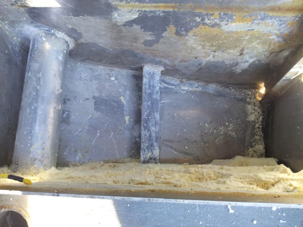
Hole at the bottom is getting bigger
Re: 24 Almar S/R
Posted: Sun Aug 03, 2014 9:37 pm
by Chaps
Nice cut, plasma?
Re: 24 Almar S/R
Posted: Sun Aug 03, 2014 9:38 pm
by Chaps
Napa Mike wrote:nice load of fish! whereabouts do you fish? I used to take an annual trip to Uclulet with my family . . . but have not gone in 5 or 6 years. I've mostly fished the Sound with a few trips to Neah Bay. The boat is looking awesome by the way.
Mike
Mike, you live in Seattle or Calif?
Re: 24 Almar S/R
Posted: Sun Aug 03, 2014 11:26 pm
by Gypseas
Chaps wrote:Nice cut, plasma?
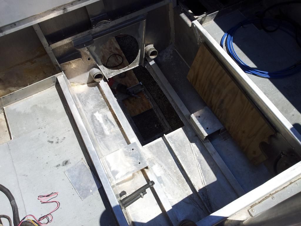
No just a circular saw and a sawsall, you can see it through the hole actually.
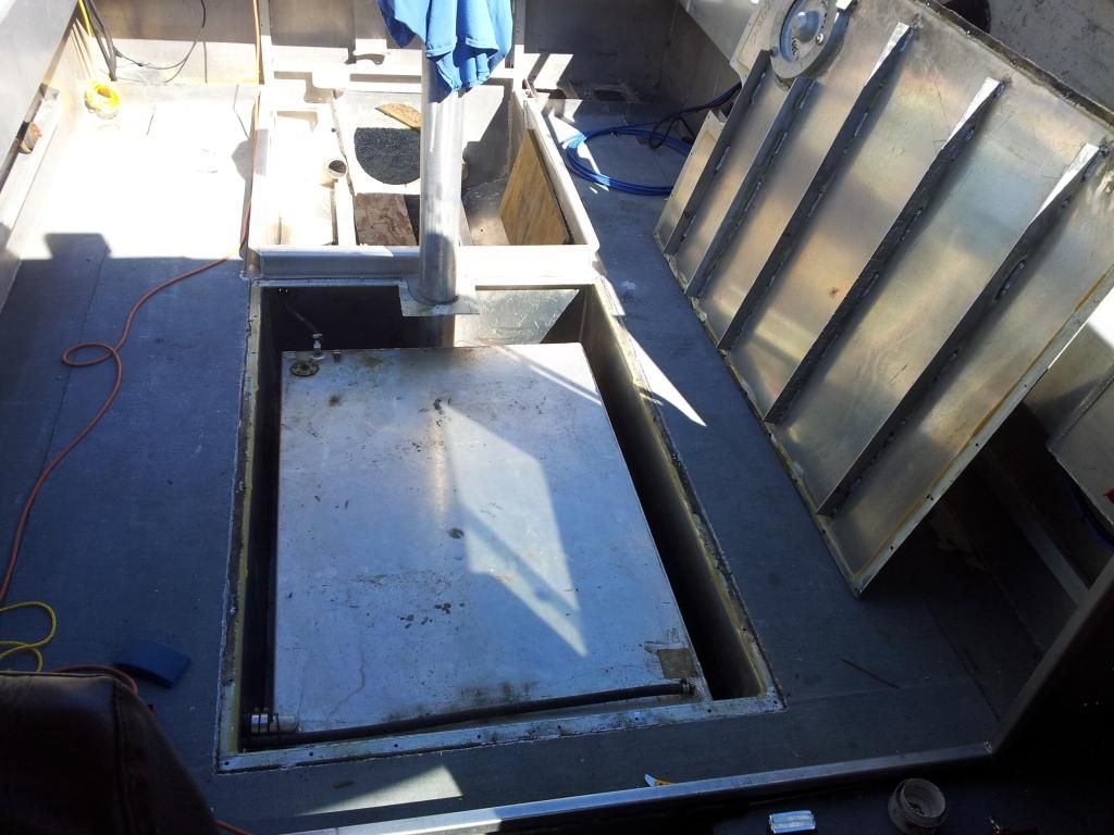
One thing leads to another and I ended up removing the gas tank cover just for a quick inspection. Quite pleased to find a 100 gallon tank behind the plate.
Re: 24 Almar S/R
Posted: Mon Aug 04, 2014 9:53 am
by Chaps
you going to leave the raised lip around the engine bay or cut it off flush? Removing the tow post?
Re: 24 Almar S/R
Posted: Mon Aug 04, 2014 3:55 pm
by pjay9
If you leave the tow post you could go into business with a tow assit endorsement. But looking at the pics that tow post doesn't seem to have much beef below...Am I missing somethingf?
Re: 24 Almar S/R
Posted: Tue Aug 05, 2014 12:59 pm
by Napa Mike
Chaps wrote:Napa Mike wrote:nice load of fish! whereabouts do you fish? I used to take an annual trip to Uclulet with my family . . . but have not gone in 5 or 6 years. I've mostly fished the Sound with a few trips to Neah Bay. The boat is looking awesome by the way.
Mike
Mike, you live in Seattle or Calif?
Hey Chaps:
not to highjack this thread--but I just moved last month from Napa back to Bainbridge Island--so we are neighbors again. The last 2 years I have been going back and forth from Napa and Seattle for work. But I could not take it anymore--particularly the time away from my family. We are all relocated to a nice house off Blakely Avenue NE (near the elementary school). So, if you ever need an extra hand to move something heavy, feel free to drop me a note. And, maybe I need to change my screen name? :-)
Cheers,
Mike
PS--I better go try fishing out of Sooke, if 4 fish in the high teens is a ho-hum day :-)
Re: 24 Almar S/R
Posted: Tue Aug 05, 2014 6:18 pm
by Chaps
Cool, PM sent
Re: 24 Almar S/R
Posted: Wed Aug 06, 2014 12:01 am
by Gypseas
Chaps wrote:you going to leave the raised lip around the engine bay or cut it off flush? Removing the tow post?
Lip stays but maybe up to 1 inch or so topped by a lid with gas shocks, for anchor rode storage, life jackets, maybe a fish hold ...dunno yet.
pjay9 wrote:If you leave the tow post you could go into business with a tow assit endorsement. But looking at the pics that tow post doesn't seem to have much beef below...Am I missing somethingf?
haha no tow assist biz, already trying to get a fishing charter off the ground while having a full time job, but who knows LOL
Napa Mike wrote:
PS--I better go try fishing out of Sooke, if 4 fish in the high teens is a ho-hum day :-)
I owe you one, boat should be ready in a month or so but yeah some days are good catching and some you have to enjoy the fishing experience.

Re: 24 Almar S/R
Posted: Tue Aug 12, 2014 11:29 pm
by Gypseas
Had the boat in the shop since Friday.
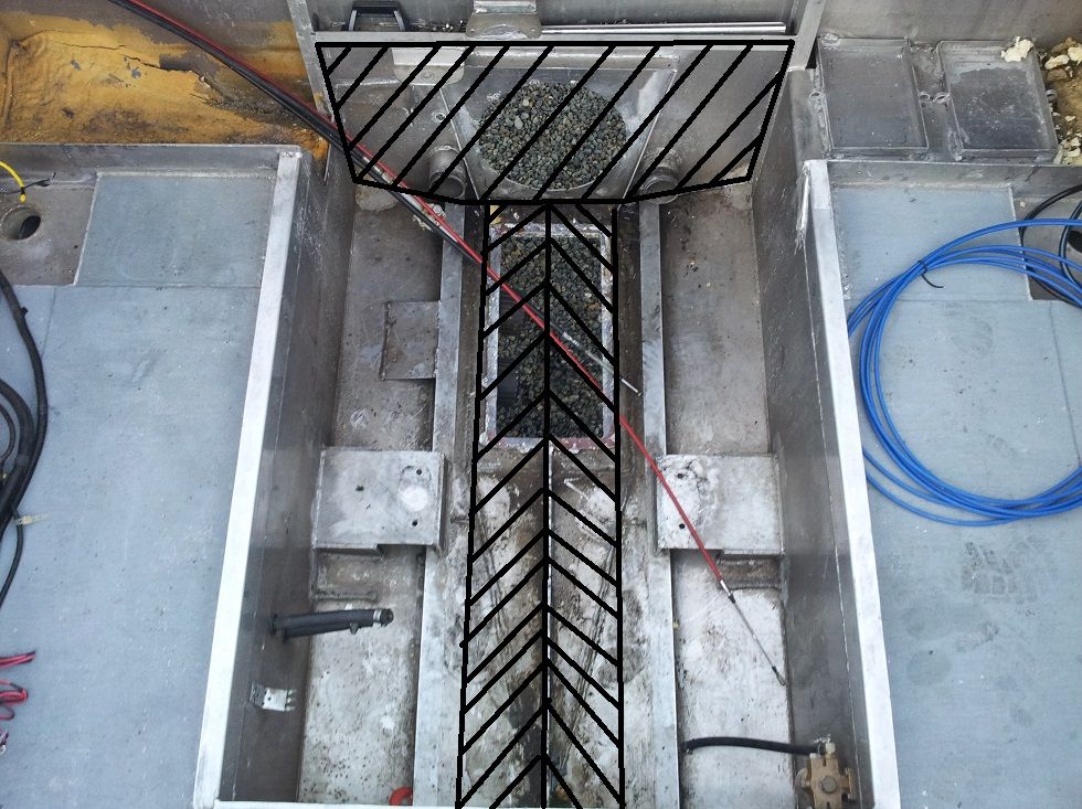
The way I was explained, the hashed area where the jet intake was will be cut and the "V" bottom restored, as well as a plate welded where transom has the round hole for the jet nozzle. Some hull stiffeners will be installed on the inside and then the motor bracket will be welded on the outside.
I really am no expert but I would have extended the walls of the motor well and restored the "V" bottom as well.
What do the expert fabricators/welders suggest, at this point I hope my guy knows what he's doing, but when I am going to hang the 300hp almost 600 lb motor I would like it to stay there

What do you guys think?
Re: 24 Almar S/R
Posted: Tue Aug 12, 2014 11:32 pm
by Gypseas
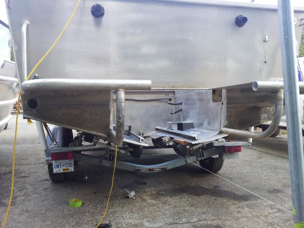
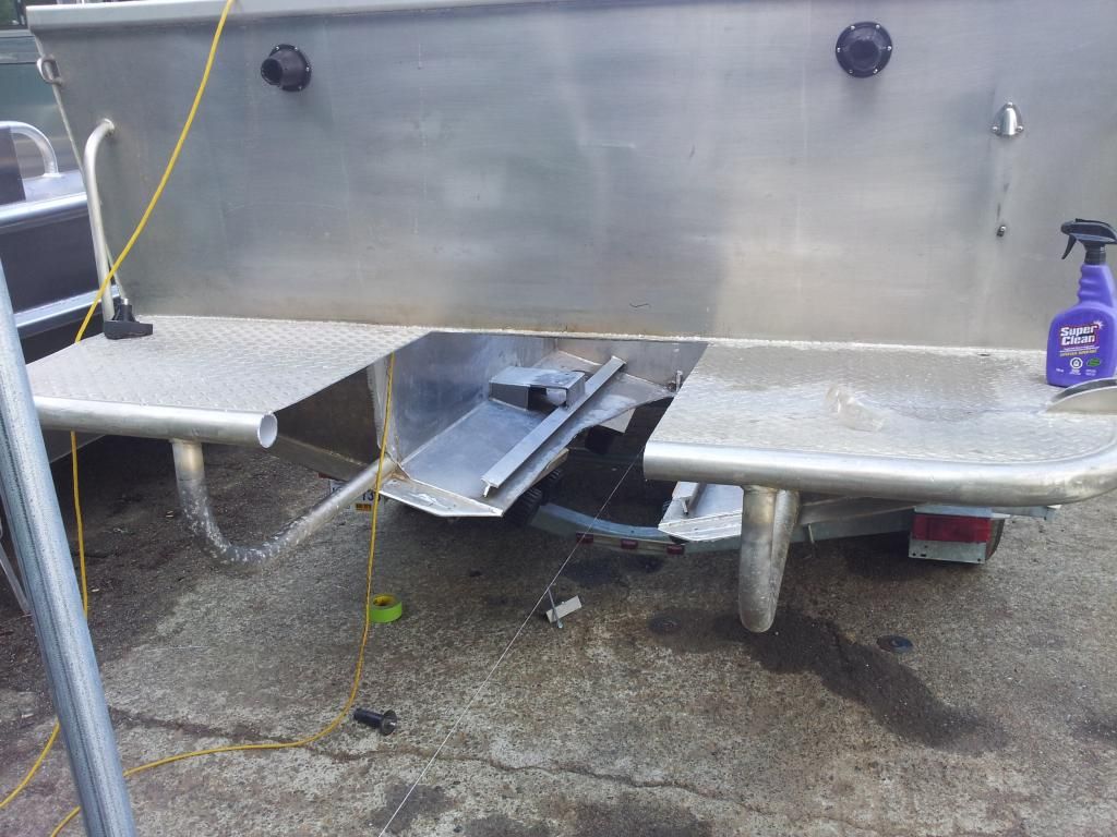
These pics were taken today
Re: 24 Almar S/R
Posted: Wed Aug 13, 2014 10:06 am
by Chaps
It's a hull extension, right? I'd like to hear Kevin's comments as to how he would approach it. I would think the motor mount stringers would be removed at some point and replaced with longitudinal framing that extends out the back but a big box properly attached might be all that is necessary particularly if the swim step system is tied in and beefed up a bit. I dunno, what is your builder saying he plans to do?
Re: 24 Almar S/R
Posted: Wed Aug 13, 2014 12:55 pm
by goatram
It looks like a hull extension. Add the bottom "V" bottom plates then add doubler plates to the inside of the new plates. Add a keel doubler to the inside of the bottom of the "V". The back I would build a box around the pipes for more floatation. Make it for a 30" XL shaft leg on the motor. My old boat had the flat bottom at the stern for a pump it did ok with the prop lwr unit. It was a 2004 NR Seahawk. I will be watching what kevin says as well.
Re: 24 Almar S/R
Posted: Wed Aug 13, 2014 3:54 pm
by kmorin
If It were my repair/rebuild I'd cut out the entire bottom in the engine compartment within about 1/2-3/4" of the longitudinal and replate that entire area with plates that extend to the stern of the new engine float/bracket. This would leave the bottom welded near but not on the existing compartment welds and make the V easy to fit without the odd shaped and overhead welded curving V of the jet plate's transition which looked like it have some severe welding on it at some point?
The two engine room longitudinals (sides) look like they'd be easy to run out to the stern of the new addition, cut the pipes entirely off except the aft most edge of the swim deck. This is now two bottom plates full length from engine room bulkhead to the new stern, two sides to this 'box' extending the existing hull longs, and then deck at the ht of the swim platform and build up the engine mount as part of the new transom.
This simplifies the entire job and the overhead welding, I'd get it jacked up off the trailer or refuse the work personally, is all inline so the edge prep is simplified by using belt sander on sheared edges. I'd prefer to TIG this but MIG would be fine, and the new bottom panels would have a couple of longs added between the VKB and the two outer engine room longs say 2"x4" breaks (if possible) coped to both ends 1" limber holes. I'd use a 1/4" x 4" VKB of sheared material in order to avoid any 6061 in the bilge if possible, it lasts OK but not nearly as well as the 5086/5083/5052 alloys will in the same application.
The keel joint can be left with a full 1/4" gap, and I'd bevel the two bottom plates to allow at least 110 if not 120 degree entry angle to that three piece, overhead weld. The bottom panels from the stern forward would be double bevel to weld inside and outside, from the transom aft, just a square joint with the two new longitudinal extension so a typical 90 deg chine joint. The bottom panels can be extended aft the transom or could be done with the same joint as the edge to edge inside fit of the two long sides.
To make it all simple I'd use 1/4" bottom for both plates and 3/16" for the longs and any new deck. The transom box/frame is another discussion as its not clear the engine shaft as near as I read? I'd tend to design the entire transom plate as a single bench built structure so I get welds in all corners, nooks and crannies with good position and control. Then I'd plan to add it to the end of the new hull extension as the last part of the build. The two new extensions could be beefed up to 1/4" as a psychological move.... but once the extension is decked, in reality they could be 3/16" without any risk of failure. The tension of the beam is the deck the compression is the 2 angled 1/4" bottom plates, the sides are just along for the ride.
Depending on the decision for the transom arrangement I like to find ways to make all the engine mounting bolts 'outside' the hull. That is- if possible, I try to find a way to keep those bolts from penetrating the new add-on volume so there is never an issue of hull corrosion, OR leak points associated to the engine mount. I often end up with small pipe TIGGED into the transom assemble of I/O's where the transom mount bolts have to end up with the nut end inside the engine room inside the hull. But if possible keeping all the bolt ends outside seems like its worth the effort to me?
This seems the simplest form to add, observing the existing framing of the original hull and the fewest fits for the effort. Weld lengths are sort of immaterial as they happen so fast they're not the labor contribution to the whole job that fitting/prep and tack-up time is.
While its being done, maybe some inside conduit for controls, electrical and fuel could be innovated to keep that out of the way? We've all got our own 'ways' of doing work so this is just my view from the photos above.
Cheers,
Kevin Morin
Kenai, AK
Re: 24 Almar S/R
Posted: Wed Aug 13, 2014 9:15 pm
by Chaps
Well there it is, can't get better free advice and consultation than that . . .
Re: 24 Almar S/R
Posted: Thu Aug 14, 2014 12:57 am
by Gypseas
Much appreciate your responses and advice gentlemen.
Kevin as always Thank You for taking the time for such a detailed step by step response.
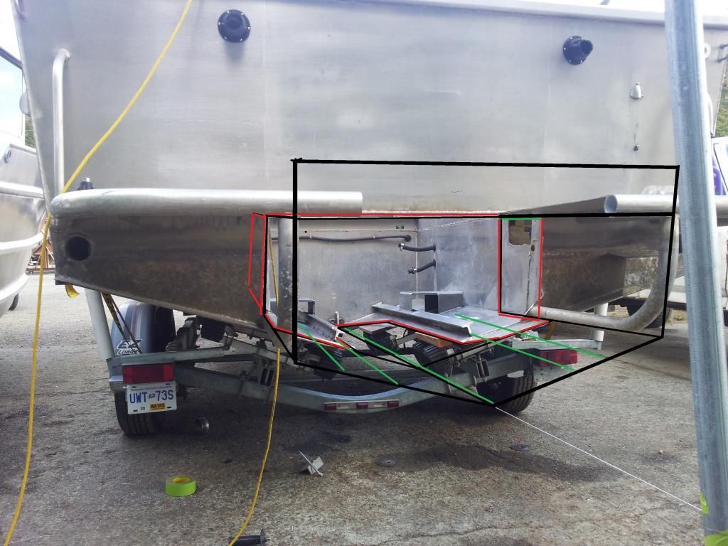
After reading it several times just to comprehend and visualize what you are suggesting this is what I came up with (apologies for the crude "paint photoshopping, I tried Rhino but man ... seems easier just to grab a pen and a piece of paper LOL)
Black lines are the edges of the bracket, red are the welds to the hull, green are hull stiffeners
Am I close?
Re: 24 Almar S/R
Posted: Thu Aug 14, 2014 2:12 am
by kmorin
Gypseas, yes that is essentially the ideas I think are appropriate.
The entire floor of the engine room/original hull and jet plate area; I'd remove. That is; extend the red/black lines all the way forward, at the bottom of the engine room sides/longitudinals to the forward bulkhead.
Replace all this bottom with two plates, these plates are common to the plane of the rest of the bottom and their centerline is correctly shown. The green stiffeners/new longitudinals are right, but I'd take out the 6061 2x2/1/4" T's with the bottom and the old engine mounts too.
The port side new side aft the transom would be common to the bottom of the hull, not leaving any pipe there or starboard. The pipes serve no purpose now the sort of fragile cast aluminum pump body is gone.
The rest seems OK, I didn't notice the openings in the engine room longs that are now shown and I agree that an overlap of these new added longs (sides of hull extension) could overlap but I'd like to look more closely at the sides of the engine room longs nearest the transom -first. I think it may be more appropriate to cut the after 6" -8" of the upper half of these longs (engine room sides) where they're cut away anyway, out. Then make the new added extension side to fill this in plane and avoid any laps. Laps have to be sealed and ideally pressure tested or they can temperature induce vacuum up water. If these plates can all be planar it would be a better job in my view.
Words are surely not the best tool here, but your sketched lines, with the exception of the entire engine room hull bottom remaining, are what I was advocating.
cheers,
Kevin Morin
Kenai, AK
Re: 24 Almar S/R
Posted: Thu Aug 14, 2014 10:17 am
by Chaps
Comment from the peanut gallery . . . when I had mine done the builder also added a couple of beefy stiffeners across the inside of the transom, one at deck level and one up higher to help distribute the motor load across the entire back end of the boat (but I didn't have a big box structure either so may not be called for in your case).
Re: 24 Almar S/R
Posted: Thu Aug 14, 2014 1:13 pm
by Sea Lion
What are your thoughts on sealing off the box created under the swim step to add floatation? A pipe could run through this area to the rear to drain the old bilge, and a second plug installed to drain the air chamber. A hatch could be placed in the swim step for access.
Re: 24 Almar S/R
Posted: Thu Aug 14, 2014 3:36 pm
by kmorin
Gypseas, Chaps, Sea Lion,
this sequence has brought up a reminder to me, of The Stern Arrangement Question and discussion again. I've decided to address it in separate topic focused not on one boat but all outboard powered, welded metal, planing hull shapes.
I hope this discussion will address lots of aspects of this area of boat design I'll add some illustrations to help make the stages clear for discussion but my goal it go "around the design cycle" and explore some of the how we got here history.
IN the mean time, any given stern arrangement could be converted to any other stern arrangement and we may, individually, find a series of good solid reasons to make the changes from one to any of the other arrangements. I'm not sure there is a 'best' stern arrangement but I'll intend this upcoming thread to explore them all to see if anyone is 'best'?
Cheers,
Kevin Morin
Kenai, AK
Re: 24 Almar S/R
Posted: Thu Aug 14, 2014 10:41 pm
by Gypseas
Todays update, didn't have my phone with me so this is what it looks like after going there yesterday with Kevin's post printed for directions

I must admit it did look good I just hope it is strong enough. Holding my breath here...
Re: 24 Almar S/R
Posted: Fri Aug 15, 2014 12:48 am
by goatram
Kevin was talking about a continuous sheets of aluminum from the fwd side of the cutout all the way out to the end under the box. Also need to enlarge the cutout so that the two plates are larger. add 2" wide doublers on the new seams after you weld in the plate. Need a couple of knee braces at the stern vertical OB engine mount.
My boat was set up for a IO engine that the second owner modified to run twin OB on. He went 6' fwd of the stern and cutout the bottom out then installed new 8' plates to make the hull run out under the swimstep. I went to my thread to get my pictures I posted of the work performed.
I also treated each compartment as a separate box with a drain pipe from the OG Bilge to the new vertical transom plate along with a pipe coupler welded in to the plate to drain the Swim Step. Each compartment has a bilge pump.
 Viewed 17722 times")
- Inside the boat looking down at the 1.5" Water manifold to supply the three pumps, the bilge pump, and the 1" drain pipe to the transom
 Viewed 17722 times")
- the Original transom as built for a 25" motor
 Viewed 17722 times")
- Here you can see the three penitrations of my Aft Vertical Engine Plate. I bought 30" engines and the boat was set up for 25" Legs. Fix was to add a 5" C Channel on top then a .250" thick plate to the back to tie it all together.
The three holes are;
1.) 1.5" for the fishbox drain.
2.) 1" for the main Bilge drain.
3.) 1/2" plug for the Swimstep drain
Kevin might want to comment if I made a wise choice or not for getting 30" Shaft legs on my motors. It does get the engine powerheads a few more inches above the water for protection.
Re: 24 Almar S/R
Posted: Fri Aug 15, 2014 8:16 pm
by Gypseas
Re: 24 Almar S/R
Posted: Fri Aug 15, 2014 8:37 pm
by Chaps
I'd suggest you get that banana peel out of the bilge asap (or don't salmon care about bananas in BC?)
alright, its probably just a yellow strap but its not good to even joke around about . . . bananas
Looks like you are about done! Looks good. As Les says, if it looks good it is good . . .
what's going on with the holes at the top of the bracket sides?
Re: 24 Almar S/R
Posted: Fri Aug 15, 2014 9:23 pm
by Gypseas
Funny I thought the same thing when I saw the yellow the screen, but yeah its just a strap LOL
The middle of the bracket needs to be recessed to accommodate the seastar hydraulic steering, so, drain holes
Should be ready tomorrow
cheers


