Conchfish AL 17.6T build

Mods and custom builds
m32825
Posts: 57
Joined: Fri Jul 21, 2023 5:51 pm

Re: Conchfish AL 17.6T build

#26

Post by m32825 »

Lower chine pockets tacked.
IMG_20240216_204723759_copy_1200x1594.jpg
IMG_20240216_204723759_copy_1200x1594.jpg (41.89 KiB) Viewed 883 times
 
​​
m32825
Posts: 57
Joined: Fri Jul 21, 2023 5:51 pm

Re: Conchfish AL 17.6T build

#27

Post by m32825 »

Once I get all the hull plates tacked in place, what's the next move? I'm leaning towards welding all the outside seams, because I imagine tacks popping if I try to flip it before doing that. What do you suggest?
 
User avatar
gandrfab
Posts: 594
Joined: Fri Mar 28, 2008 12:33 pm
16
Your location: Edgewater Fl
Location: Edgewater Fl

Re: Conchfish AL 17.6T build

#28

Post by gandrfab »

Weld out sequence is part of the design plans?

I think I would start in the middle of hull and weld seams, backstep welding out.
Each individual 4" to 6" weld, welding towards the center 
Skipping around welding all longitudinal seams simultaneously from center out.

Hope kmorin chimes in.

This video give a good example except it looks like he shows beckstep welding from corner to end or end to end.
Where I thing center out would be more beneficial.

  https://www.youtube.com/watch?v=KUXoAtCapdQ


This are good books to read. 
00.png
00.png (632.71 KiB) Viewed 793 times


m32825
Posts: 57
Joined: Fri Jul 21, 2023 5:51 pm

Re: Conchfish AL 17.6T build

#29

Post by m32825 »

This hull has been built many times with non alloy materials, but this is only the second one built from aluminum. The designer is not an expert on welding, so we're trying to figure it out.

I have Pollard's book and watched all the distortion videos by the guy you recommended. The back steep method makes sense. Thanks for the pointers!
kmorin
Donator 08, 09, 10, 11, 12, 13, 14, 15, 16, 17, 18, 19, 20, 21, 22, 23, 24
Posts: 1745
Joined: Mon Aug 18, 2008 1:37 am
15
Your location: Kenai, AK
Location: Kenai, Alaska

Re: Conchfish AL 17.6T build

#30

Post by kmorin »

m32, have you welded a skiff before?  Just chking to see how detailed to try and explain my point of view re; skiff assembly.

Also, just re-read the thread and would like to know if the hull bottom panel seams have longitudinals inside at or near the seam?  I'm referring to the seam in the bottom panels that is below the inner most chine and above the keel?  Not sure of the body section detail in that area and seam and it differs day and night from the other seams I can see in the photos. 

If this seam is just a 170 or 180 degree flat to flat seam - it might be best to discuss that particular seam as soon as you can, perhaps even before adding the bottom panels?  Especially as you've remarked the current metal plans provider isn't a welded skiff builder?

I'd remark more if you had time before you have to weld, if it will help?  I've built a few skiffs so the list of mistakes I've made- you're free to avoid if your work schedule allows?

Cheers,
Kevin Morin
Kenai, AK
kmorin
m32825
Posts: 57
Joined: Fri Jul 21, 2023 5:51 pm

Re: Conchfish AL 17.6T build

#31

Post by m32825 »

Hi Kevin,

I have not welded a skiff before. I'm the poster child for "that guy with no welding experience trying to build a boat" but it's the only way I was going to get this hull in aluminum. It's for inshore fishing in an area known for oyster bars and limestone bottom. My usual boating community has plenty of non-alloy builders and even a designer or two, but aluminum is still a rare beast and there isn't much tribal knowledge.

No longitudinals, just crossways frames. I'm working on putting the rest of those in place now.

I'm grateful for any help you can offer, want to come to Florida and weld? 

    -- Carl
 
kmorin
Donator 08, 09, 10, 11, 12, 13, 14, 15, 16, 17, 18, 19, 20, 21, 22, 23, 24
Posts: 1745
Joined: Mon Aug 18, 2008 1:37 am
15
Your location: Kenai, AK
Location: Kenai, Alaska

Re: Conchfish AL 17.6T build

#32

Post by kmorin »

m32',
Just discussing the seam in the twin bottom panels: that seam, if I'm correct (?), is unsupported and is visually very nearly 'flat' one sheet edge to another?  Pls confirm this as all the other seams in the hull shown are of a very different class of weld joint.

To my eye- that seam in the bottom is not even needed- I think the bottom panel will conform to the shapes shown in the x-verse frames just fine? If I understand correctly (?) this seam was designed in to help make the bottom shaping/forming/installation "easier" than if the bottom panels were a single panel (one per side instead of 2 per side?).  Before welding the rest of the hull, and before finalizing your bottom panel install I'd seriously consider re-thinking this seam.

1.  Butt welding sheet to sheet w/o any long-wise support in sheet metal is very tricky for experienced welders and invites a disaster (IMO) for the new builder/welder.  I describe the seam as a butt weld even though the sheet is not dead flat - and has some small angle between the two sheets' edges.  However, the way the two sheet edges will react to welding is to wrinkle the seam since there is no structural resistance to the heat contraction of the edges as they're shown.

2. If the two sheets are laid out on a flat table (unwelded) can you show their shape in an image post?  I'd line up the after 1/2 of both panels (should be a straight line on each panel) and show the two 'orange peels' or tapers and how much they're divergent.  This will help understand what shape is being attained when installed.

3.  Can you consider a 'trim' of the outer panel's inner most edge to install a flat bar vertical to the hull surface (inside) and at the outer edge of the inner most hull panels?  By trimming the outer panel the thickness of the flat bar (say 3/16" or 1/4"?) evenly- you'd form a U with the two adjoining sheet edges the sides and the flat bar's outer edge the bottom of the U shape.  This could be a weld groove and filled w little or no hull shape distortion but.... requires installation soon and notching of the frames to accommodate the longitudinal FB.

4. In the mean time.... Please, take any two 12" long pc of the hull plate (1/8"??) and clamp them at 90 deg. and edge-to-edge then tack and weld that coupon and post a pic?  Next, and more important, please take any two 12" x 4"-8" pc.s of scrap/off-cuts and butt them edge to edge and make a small groove in the two edges/chamfer the edges 70% thickness, hold them at 5 deg. to one another, tack and weld that seam then post pics?  This exercise will illustrate my concerns for this bottom panel hull seam.

5. You might also help anyone offering ideas and their experience to explain your welding equipment, including wire, alloy & size; gun type configuration and if you have TIG or not?  It's good to discuss bead type in detail for each weld, and to discuss tack handling prior to welding.

Since we're getting somewhat detailed, please try and keep replies somewhere related to the numbers- or state the topic you're addressing as I've had lots of confusion online, in the past, trying to be of help when the level of written communications became too complex to really get much useful information across.

Have to decline a trip to the warmer latitudes, thanks, as my health has gotten a bit less reliable now that 70 passed a few years ago.

Cheers,
Kevin Morin
Kenai, AK
 
 
kmorin
m32825
Posts: 57
Joined: Fri Jul 21, 2023 5:51 pm

Re: Conchfish AL 17.6T build

#33

Post by m32825 »

Hi Kevin,

This boat is made from laser cut .125" 5086 sheet and 6061 extrusions. I'm using .035" 5356 solid wire in a spool gun with 100% argon shielding gas. I also have 5356 filler rod for TIG welding. My MIG and TIG machines are both Primeweld brand, a relative newcomer to the market.

​​​​​​The hull has 1.5 degrees of deadrise at the transom for shallow water operation, but transitions to a more angled bottom going forward. I think you are right that there could be fewer pieces, but might need a big brake to put a crease down the middle to help fit up near the front. The picture below shows the center hull panels, the tape is extended three feet for scale, that's about how much doesn't touch. The points of the panels are ten inches apart.

 I'm on board with making changes to align the hull plates, I already have enough experience warping things to picture the outcome you describe. The frames have mouse holes for access to those joints, what dimension flat bar are you thinking?

    -- Carl
IMG_20240225_163650266_copy_1200x1594_1.jpg
IMG_20240225_163650266_copy_1200x1594_1.jpg (24.26 KiB) Viewed 726 times
 
kmorin
Donator 08, 09, 10, 11, 12, 13, 14, 15, 16, 17, 18, 19, 20, 21, 22, 23, 24
Posts: 1745
Joined: Mon Aug 18, 2008 1:37 am
15
Your location: Kenai, AK
Location: Kenai, Alaska

Re: Conchfish AL 17.6T build

#34

Post by kmorin »

m32,
The two panels I'd like to see in the photo are not the two center, inboard bottom panels adjacent the keel as shown. They are the panel to the left in the photo and the panel to the left of the paired center-line panels.  However the alignment is correct-tight together, aft where they're straight.  Was trying to see how much the orange peeled bow cuts spread and imply the purpose of that seam.  It is possible the designer got feedback that said the plate couldn't be developed in one piece (? might check with him??) but marine software rarely accepts the level of compound convex curvature that can be pulled into a 1/8" sheet.

Will your welding system permit 0.030" wire or even 0.023" wire?  The 0.035" can work but won't give the best results as it takes a bit more wattage to run than is needed for 0.125" sheet.

Also, you note the 6061 alloy is used for the extrusions but I see a sharp cornered (architectural pattern extrusion) "angle" at the lower chine location and that is (most) often supplied in 6063 alloy? Just checking - 6063 is not suitable for immersion in salt water - splashing it may be OK but that alloy has a copper content fraction that creates an 'internal corrosive battery' in the native material.  Worth checking the alloy of those two odd legged angles?

Cheers.
Kevin Morin
Kenai, AK
 
kmorin
m32825
Posts: 57
Joined: Fri Jul 21, 2023 5:51 pm

Re: Conchfish AL 17.6T build

#35

Post by m32825 »

Hi Kevin,

Man, communication is hard! Fortunately we can try again...

Pictures below with all panels side by side, three feet of tape out for scale. The center panel and the one outside it begin to separate almost immediately. The gap grows to a maximum of 3/16" before coming back.

I have all the supplies for .030" just haven't tried them yet. Will prioritize that and check into .023" supplies.

I've got channel, angle, flat bar and pipe, all of it 6061 according to the markings printed on them by the mill.

-- Carl
 
 
IMG_20240226_222511018_copy_1200x1594.jpg
IMG_20240226_222511018_copy_1200x1594.jpg (26.87 KiB) Viewed 695 times
 
IMG_20240226_222530815_copy_1200x1594.jpg
IMG_20240226_222530815_copy_1200x1594.jpg (25.12 KiB) Viewed 695 times
 
IMG_20240226_222559496_copy_1200x1594.jpg
IMG_20240226_222559496_copy_1200x1594.jpg (29.51 KiB) Viewed 695 times


kmorin
Donator 08, 09, 10, 11, 12, 13, 14, 15, 16, 17, 18, 19, 20, 21, 22, 23, 24
Posts: 1745
Joined: Mon Aug 18, 2008 1:37 am
15
Your location: Kenai, AK
Location: Kenai, Alaska

Re: Conchfish AL 17.6T build

#36

Post by kmorin »

Carl,
this set of images shows a major (problem) question I have of the lines plan and plate development of the bottom. 

Image # 1 shows the panels all aligned next to one another and that confirms the two panel design is not likely needed? 

Image #2 shows a VERY small shape separation at the bow- this means the 'bulb' or bend of the entire forefoot region is so small it may well come from one single panel?  There are tests you can do to learn the answer to that.

Image #3 is the bad news.  The gap between the two sheet edges- not at the bow- once mounted to the hull frame and tack edge to edge will result in a 'hog' or hollow or 'small waist'  in the bottom shape.

Let's review a bit.  The keel is a straight line (pls confirm - it looks straight as the two center panels touch along what looks like a line?).  In other photos you show a lower chine flat- formed by an angle (that I have questioned the alloy of- you've confirmed this odd legged (3"x6"??) chine flat angle is 6061).  However, looking at the after 10'-14' of that vertical edge/leg of the angle- is seems like a straight line?

Now, the above facts may not be confirmed that is; I may not understand what's present, so.... before making any hard conclusions it would be good for you to confirm those two facts. 

NOW... for the reason for this current conclusion that your sheets (as cut) offer a major shape problem.  If the two keel edges of the inner most panels meet in a line, and the outer panels' outer edges are straight lines for the after 2/3 of the hull(?) (need to confirm these suppositions) THEN in order to touch one another the two bottom sheets will have to be pressed (downward as inverted) together to form a seam. THat pressing together looks to me like it will create a long slow 'bow' or cup in the bottom panel? 

I'd want the bottom of this skiff to be slightly rounded chine to keel, and the lines on those cylindrical shapes to be very parallel.

Please confirm that what I'm seeing - the gap between the edges of the inner and out panels - just 6'-10' forward the transom- is 3/16"?  (!!)  IF so then you may want to contact the other builder who's used these panels and learn more about the bottom shape?  Also, if the lines of the skiff are available you might be able to look at the waterlines from the keel to the first chine and see if all the buttock lines are smooth and parallel aft the 1/3 or Master Station? 

Hope this comes through in text?  otherwise I'd have to try sketches - but this item should be addressed before you go further (including installing the bottom four panels.

Cheers,
Kevin Morin
Kenai, AK
 
kmorin
m32825
Posts: 57
Joined: Fri Jul 21, 2023 5:51 pm

Re: Conchfish AL 17.6T build

#37

Post by m32825 »

Kevin,

The keel is a straight line, and the hull plates on either side of that line develop more curvature as they go forward. Here are a couple shots of the frames to provide a sense of the shape.
IMG_20240227_232207916_copy_1200x1594.jpg
IMG_20240227_232207916_copy_1200x1594.jpg (45.84 KiB) Viewed 638 times
 
IMG_20240227_232243730_HDR_copy_1200x1594.jpg
IMG_20240227_232243730_HDR_copy_1200x1594.jpg (45.94 KiB) Viewed 638 times
I was confused at first about the angle you were referring to in relation to the chine because I do have 6061 angle elsewhere, but all of the hull plates are .125" 5086. That chine is 5086 plate and has some rocker to it. Here's a six foot length of flat bar resting on top to show the curve.
​​​
IMG_20240227_232318186_copy_1200x1594.jpg
IMG_20240227_232318186_copy_1200x1594.jpg (40.37 KiB) Viewed 638 times
I don't think the 3/16" gap we're seeing when the plates are flat is a problem when they are in place. I can't explain why, but the gap disappears. I'm pointing at the spot we have 3/16" gap when flat. Looks pretty good.
IMG_20240227_232942584_copy_1200x1594.jpg
IMG_20240227_232942584_copy_1200x1594.jpg (31.95 KiB) Viewed 638 times
 
IMG_20240227_233000552_copy_1200x1594.jpg
IMG_20240227_233000552_copy_1200x1594.jpg (26.73 KiB) Viewed 638 times
 
 
kmorin
Donator 08, 09, 10, 11, 12, 13, 14, 15, 16, 17, 18, 19, 20, 21, 22, 23, 24
Posts: 1745
Joined: Mon Aug 18, 2008 1:37 am
15
Your location: Kenai, AK
Location: Kenai, Alaska

Re: Conchfish AL 17.6T build

#38

Post by kmorin »

Carl,
first the chine flat made of an extrusion??  I see the bar showing that flat has rocker and so it may rise as a buttock line forward from the transom, can't tell w/o the lines plan.  BUTTT.... you refer to it as 5086- so the angle extrusion is 5086 or there is a chine flat plate and a vertical flat bar tacked inside??

Very confusing, image.  I'd have said the sharp 90 deg corner resulted from an extrusion... can't bend 5086 in a sharp 90 or the inner edge would be lined with stress cracks.  SO I'll keep believing its an extrusion- the horizontal chine flat and the vertical bar are one piece... not formed on a press brake- that implies that you were able to source 5086 extrusion of this odd legged angle?  Would like to understand more about that but my remarks are about the bottom panels. Could post an image of an ink stamp on this piece?

Onward

There are two cases for the bottom panels 'edge to edge' butt welding seams discussion.  The first case is forward where they begin to curve into forefoot of the keel and about 36"-40" aft the bow stem for the mid panel seam.  This area may be able to weld (depends on bead) w/o joint support in the form of a longitudinal flat bar, but I'd put one in there if it were me using these bottom panels.

The second case of bottom panel seams is aft those two forward areas where the run of the hull is essentially straight lines.  In that area aft- I'd add one of two types of support.

Type One support is a set of frame to frame- cut lengths of 1/4" x 1-1/2" bar that was tacked to the frames at the ends of each bar- AND then tacked to the inside of the bottom center line panels' outer edges.  These would stiffen the seam prior to welding so the butt joint- edge-to-edge welds designed could be welded with support from lifting off the flat bar or dipping into the bilge- making a local 'cup' in the bottom due to weld warping.

Type Two choice of support would be continuous flat bar notched into the frames, one, at the keel that would support the keel line weld, and  another at the mid panel seam between the 1/2 bottom panel pieces shown. So three flat bars in this case that were installed to the outer edge of the inner bottom panels.

In Type 2 you'd trim the outer panel's inner edge by 3/16" (not a full 1/4) to allow the edge of the flat bar to be a weld back up to the hull seam and the bars would be permanent part of the boat. 

In Type 1 the after bulkhead to bulkhead (x-verse frame to frame) temporary bars would come out after the hull was welded.

In the Type 1 I'd leave the forward curve cut seam back up bars in also.

IN both cases I'd want to bevel the edges of the butted sheets to take off the outer upper 'shoulder' of a square cut edge- so the weld arc wouldn't 'go to ground' on the upper outer edges of these welds, I'd want to bevel the sheets two edges to get the arc deeper into the groove formed, especially important if you're going to trim the outer sheet and use the Type 2 seam support scheme. 

All of this is because the sheet joint looks very ripe for contraction as its unsupported between frames and 1/8" material just won't stay 'clean' like it shows in the cold layout photo you include; UNless there is some seam support.  Even then the welds will be pretty tricky- compared to outside corner or 90 deg. fillets as shown in the rest of the skiff.

Cheers,
Kevin Morin
Kenai, AK


kmorin
m32825
Posts: 57
Joined: Fri Jul 21, 2023 5:51 pm

Re: Conchfish AL 17.6T build

#39

Post by m32825 »

Kevin,

More later, but here's an inside view of the chine assembly.

-- Carl
IMG_20240218_104118288_HDR_copy_1200x1594.jpg
IMG_20240218_104118288_HDR_copy_1200x1594.jpg (29.31 KiB) Viewed 629 times
 
 
m32825
Posts: 57
Joined: Fri Jul 21, 2023 5:51 pm

Re: Conchfish AL 17.6T build

#40

Post by m32825 »

>Could post an image of an ink stamp on this piece?

I checked the ink stamps when the parts arrives, but they've been wiped down with acetone since then. Here's the relevant part of the invoice:
Screenshot_20240228-170716_copy_785x244.png
Screenshot_20240228-170716_copy_785x244.png (38.19 KiB) Viewed 613 times


m32825
Posts: 57
Joined: Fri Jul 21, 2023 5:51 pm

Re: Conchfish AL 17.6T build

#41

Post by m32825 »

Seems like it would be easier to make a continuous piece (Type 2) approximate the desired flow of the bottom than a bunch of individual pieces (Type 1). Questions:

1) What size flat bar for Type 2?
2) Can I use 6061?
3) When welding out all seams, Inside or outside first?


kmorin
Donator 08, 09, 10, 11, 12, 13, 14, 15, 16, 17, 18, 19, 20, 21, 22, 23, 24
Posts: 1745
Joined: Mon Aug 18, 2008 1:37 am
15
Your location: Kenai, AK
Location: Kenai, Alaska

Re: Conchfish AL 17.6T build

#42

Post by kmorin »

Carl,
No need to show print stamp on chine flat once you show it's a tacked up pair of bars-plates-sheet outlines & NOT an extrusion! (I) Hate those T-joint fillets instead of outside corner joints where inside edges meet and form a natural full depth edge groove for a weld- but you have what you have.

1.  If you install a continuous flat bar- Type 2 as described- you can use 1/4" wide bar and it only needs to be 1-1/4" deep could be deeper aft-but that would make pulling it into a fair curve in the forward 4' more work. Welding sequence remarks coming.  Notch TOO SMALL with a saw.... then 'file out' to allow the bar to slip into the frames' notches. Can use a small adjustable square held onto the inner sheet's outer edge- (cold clamp inner panel on for this step) to mark the notches- both cuts could be under the sheet's edges.  Can drill a hole at the bottom of each notch, then file out the corners.

Holding a flat bar over the top of the frame (transversely) will show when the notch is deep enough?

2.  6061 T-6 is the most common alloy for flat bar in most markets, and would work fine to back up that hull seam.

3.  Have some remarks on welding coming, however a boat project, here, is taking most of my time to get sketches for forming and additions to the (welded) boat in my shop.... so will be most of the evening to get the welding remarks finished, edited and posted.

Cheers,
Kevin Morin
Kenai, AK
 
kmorin
kmorin
Donator 08, 09, 10, 11, 12, 13, 14, 15, 16, 17, 18, 19, 20, 21, 22, 23, 24
Posts: 1745
Joined: Mon Aug 18, 2008 1:37 am
15
Your location: Kenai, AK
Location: Kenai, Alaska

Re: Conchfish AL 17.6T build

#43

Post by kmorin »

Carl,
If you turn the hull before welding the outer seams (?) will the building form go over too? If not (?) then I do understand some risk to deformity- but decent tacks shouldn't come undone??

It would be fine to weld the bow stem/keel seam from sheer to the aft end of the forefoot (keel seam) and a few inches, aft, along each of the many seams intersecting there as a 2”-3” weld; each. Next, weld the transom seams outside- from gunwale to gunwale. Then weld along each of the fore aft seams for 2”-3”. To do the transom welds; start at the keel/tunnel and weld from the center outward and do a 4" on the port, then 4" on the starboard. Once the tunnel's after lower corners are welded- jump out to the first chine angle and do both sides, then out to the next chine and weld both sides.  Once all the intersections of long seams to the transom are welded in the transom plane- it won't matter if you fill in any longer welds that weren't within 3”-4”of an intersection seam. This method will slowly (w/o distortion) trap the ends of the major hull panels and angle changes of hull-shapes-to-transom-joints so they can't shift- allowing the hull to twist.

I would work symmetrically about the keel plane to install these initial welds to avoid contraction misshaping the stern. The forefoot and bow stem’s welding will not twist the hull.

These two sets of seam welds, bow stem/keel & transom to hull long seams, will keep the 'true triangle' of the hull so there is no twist (will assume there's none as she's in the jig?)

Next, I' make a hull seam 'story stick' or weld layout pattern for the long seams. I usually weld in three separate lengths; 4", 6", & 8" long welds when doing hull seams. The first pass of all seams is a series of 4" staggered welds; then I trim the starts & stops so the future adjoining welds will tie in w/o cold lap. Second pass, in my hull welding, is a series of 6" welds and the ends gouged to accommodate future tie in's fore and aft. Third, I fill in the left over spaces w 8" long welds that tied into the previously installed and back gouged welds.

A story stick would have a spacing of 4", 8", 6", 8", 4"; rings of black marker will allow you to lay the stick below the weld seam and put marker dots at the beginning/end of each spacing interval. Now when you weld you can see the black dot coming up to end that first 4" weld. A story stick allows you to plan your passes - first the 4" are done skipping every other one- then do the opposite side.  Next do all the hull seams in a similar 'first pass' scheme.  Stagger the welds from the first to the 2nd to the 3rd 4" weld in subsequent seams from bottom/keel to shear.  So you'd avoid putting all the #1 4" welds stacked one above another at the transom and then a couple feet further forward you could end up with a stack of 4" welds one above another to the sheer!  Instead stagger the story stick layout count so the welds are spread along each seam differently and only symmetrical form side to side on any given seam. This will avoid over contraction and distortion.

I personally prefer to chain weld hull seams. I'm right handed and usually weld toward myself- from an arms extended initial position pulling the gun toward and in front of me. I do this to see under the gas cup as I lead the puddle from arms extended to about middle of the body and that seems to give good visual overview under the gas cup as well as repeatable movement. I put the back of my left hand on the hull and cup the goose neck nozzle in my left hand's fingers so I have a steady rest to guide the weld.

My method on a skiff like this (super high long-seam count) would be to begin at the stern on the port side and weld the first 4" toward the transom tying into the previously installed few inches of long wise hull seam weld done at the transom or bow. Next, I'd move to the third 4" space and weld from the bow end of that spacing toward the stern- and continue skipping every other one; until there are no more 4" welds to do on that pass of that particular seam. Then I'd reverse that on the starboard side by welding the first 4" space aft the bow - direction would be aft to forward tying into the short bow stem seam weld and continue to the 3rd 4" space aft. This series of welds would be done aft end first welded toward the bow the reverse of the first chine seam above, which began at the stern and skipped welds going forward; now you’d start at the bow stem and skip welds progressing aft but welding toward the bow in each weld.

Once the bow and stern ends of the hull panels are joined (above) there is no risk of distorting the hull unless you weld onside w/o balance to the opposite. However, there is a consideration in your design that should be taken into account.

The types of weld joints I use are inside edge to inside edge; you show those on the transom to topsides joints and the transom to chine flat joints. These weld fit ups allow a simple ‘drag’ type of bead to be adjusted in heat, Wire Feed Speed, angle of lead of the wire to the seam (dragging toward your chest from arms extended) and result in good penetration while leaving a very nicely proportional low crown bead outside. In your hull, with all the T-fillets formed by butting one pc. of hull to another (like the chine flat to vertical bar shown in a recently posted image) MAY require you to pattern/whip/stack dimes weld instead of a drag?

For the edge-to-edge welds 0.030” wire would work (even 0.023-25” wire will work in 1/8”) but... in a T-fillet your bench tests may show you can’t get the wattage on the 0.035” wire needed to give a good quality drag weld due to the increased cross section of the parent metal you’ll have to heat up to get fusion. You may need to propane heat the hull in preheat depending on the bead type and method of applying the welds you choose. I’d want to bench test the power supply, gun and operator!! to confirm the hull welding appropriate for each of the two types of seams I can identify in the pictures posted. Hope this helps to begin a welding discussion? 

Trying to give details about exactly how I do it, but take into account the differences between my designs and this one. Let me know if we need to go over this more?   You can weld the bow and stern then put a couple of series of hull welds (first, 2nd & 3rd of the 4" passes) and then safely turn the hull as it will not deform after that much welding.

Cheers,
Kevin Morin
Kenai, AK

 
kmorin
m32825
Posts: 57
Joined: Fri Jul 21, 2023 5:51 pm

Re: Conchfish AL 17.6T build

#44

Post by m32825 »

Wow... that's a lot for my tiny brain to process, but it's exactly what I was hoping for! I'm going to have to circle back on it a few times and gradually digest it. In the meantime...

I'm working on getting flat bar. Slotting the frames means I have to nail alignment with the edges, could I slot the flat bar instead? Then I'd be able to slide it into perfect alignment before tacking it to the frame. The mouse holes along those seams are about .75" deep, so I'd notch the flat bar half an inch where it crosses the frame. Picture it as a middle ground between Type 1 and Type 2, call it Type 1.5? 

Here are my welder specs, I'm plugging it into 220V.
IMG_20240229_085814536_copy_1200x1594.jpg
IMG_20240229_085814536_copy_1200x1594.jpg (40.75 KiB) Viewed 553 times
 I got .030 loaded into my spool gun and experimented with settings. Seems like 19.5V and 400 ipm is in the ballpark. Here's a rogue's gallery of welds from this morning.
IMG_20240229_100308833_HDR_copy_1200x1594.jpg
IMG_20240229_100308833_HDR_copy_1200x1594.jpg (42.13 KiB) Viewed 553 times


kmorin
Donator 08, 09, 10, 11, 12, 13, 14, 15, 16, 17, 18, 19, 20, 21, 22, 23, 24
Posts: 1745
Joined: Mon Aug 18, 2008 1:37 am
15
Your location: Kenai, AK
Location: Kenai, Alaska

Re: Conchfish AL 17.6T build

#45

Post by kmorin »

Carl,
What does this system look like using 0.035" wire?  The welds shown have excessive over spray- tiny droplets on the material surrounding the weld bead...that condition usually indicates the weld arc length is too long- so I'd want to increase the wire feed speed and shorten the arc length and stick out of the wire from the contact tip to the work.

Move the gas cup closer and try for narrow, smaller beads you show in the test plate.  Also, mock up the T-fillets & weld some of them and any outside corner welds (in the hull's weld out) and show those welds- concentrating on the types of drag beads shown- narrow, hot, fast travel and not wide 'mushroom' headed beads that have sides which cold lap the welded parent metal.  Beads should have flowing lines into the welds' ripples (not patterned welds) that show the heat of fusion was reached and the droplets in the arc transfer all flowed into the molten parent metal-  not having overhanging or bulging sides.

In almost all continuous seam welding done in passes or 'lifts', there will be other welds tying into the welds put down in earlier passes.  So the ends of the majority of welds can be 'wiped out' by the following technique.

When you're coming to the end of a weld, let go of the trigger of the gun/torch and at the same instant swing the torch tip very rapidly away from the weld- along the line of travel of the weld. This technique will leave a diminished weld puddle spread over 1 to 2 puddle widths of length but won't leave a crater. All the welds you're showing have a very pronounced crater at their ends and this is from holding still while stopping/ending the weld.

To avoid a crater (that has to be 'cut out') use the 'wipe out' technique where the arc is extinguished as it's wiped away from the weld's end.  The goal is to reduce the prep work for the next pass to either start on a non-cratered area of the previous weld or tie-in/end at a non-cratered previous weld.

Cutting the starts (and stops if you don't 'wipe-out' the craters) can be done with either a meat axe type tool or a rotary carbide burr on a die grinder.  Both methods will result in trimmed welds ready to weld for the next passes' tie in or start.

Image

Image

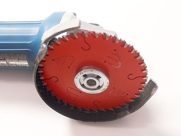
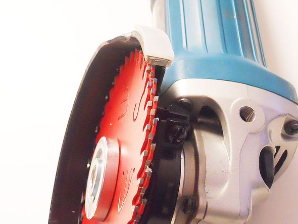
Above is a 3 blade meat-axe/widow maker/trim tool that is very safe and can be used with only two blades. I use the smallest Diablo brand blade with a 19-20mm mount hole and I welded the two extensions onto the original steel blade guard housing to insure this tool has a set of steel plates top and bottom that you can pivot the tool's blade on.  Also they decrease the amount of circumference of the blades can reach metal.  This tool will allow a very well controlled 'back chipping' of the inside penetration of any welds that need to be trimmed inside the hull- prior to back welding areas where the outside seams are already welded.

Because there are so many teeth in contact with the tacks, welds, boat's metal when trimming this meat-axe will actually ride safely on the work and never grabs the metal like some versions of this tool do. 

All tacks, weld starts and weld ends if needed, should be dressed down before welding over, tying into or ending on as the sudden change in the thickness of the welded metal at a tack will 'chill' or prematurely freeze a MIG puddle so they have to be dressed correctly in order to get uniform quality welds.

Image
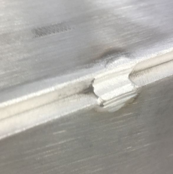
 image showing a tack dressed down to the actual holding material; ready to weld over.

Image

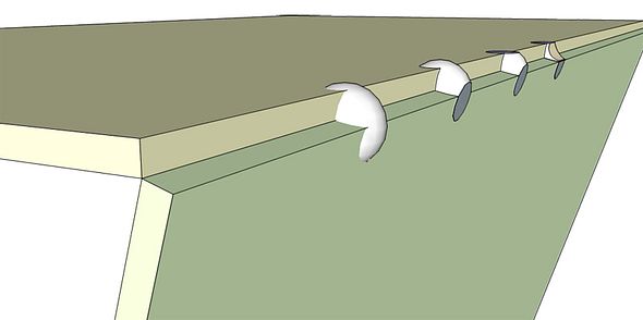
Sketch of a tack being dressed down ready to weld. The three operations ; flatten to side face, flat to top face, and finally, cup to reduce cross section are shown for this 'tack'.  Same applies to T-fillet weld in order to get the volume of metal in the tack down to a minimum so when the weld (a continuous related rate of heat, filler, travel speed and freeze rate) comes by- the tack doesn't cause a cold spot or lack of fusion. In a T-fillet there's only a scooping cut no facing to adjacent parent metal as shown in this sketch.

Hope these further notes help your planning for the weld out?

Cheers,
Kevin Morin
Kenai, AK


kmorin
m32825
Posts: 57
Joined: Fri Jul 21, 2023 5:51 pm

Re: Conchfish AL 17.6T build

#46

Post by m32825 »

Kevin,

Great notes feedback and information for my welding journey. I'm worried that trying to herd me in the right direction is costing you sleep, though. Your help is much appreciated.

I have to focus on work Friday, but should be able to pick up my flat bar and run beads to try your suggestions on Saturday.

-- Carl
kmorin
Donator 08, 09, 10, 11, 12, 13, 14, 15, 16, 17, 18, 19, 20, 21, 22, 23, 24
Posts: 1745
Joined: Mon Aug 18, 2008 1:37 am
15
Your location: Kenai, AK
Location: Kenai, Alaska

Re: Conchfish AL 17.6T build

#47

Post by kmorin »

Carl, I'll be OK, I think?  Seems like all I do is sleep!

Regarding flat bar- I would want it to bend to the shape smoothly and notching the bar- will not make that happen- it will kink at the notches. The purpose of the Type 2 bar is permanent- Type 1 was in segments to remove after the seam was welded. 

To fit the bar's notches (Type 2) clamp one side of the center line panel in place on the frames near the keel and at the outer edge of the panel- then put a small square, at 90 to the keel plane and laying on the sheet mtl. down the frame and mark. This mark would be one line of two cuts.  You'd cut INSIDE- toward the keel on the first cut line.  This would move the inner most edge of the seam backing flat bar inside underneath (toward the keel) of the actual edge of the sheet.

The 2nd cut line is 1/4" (tight) from the first and will end up just outboard/away from the keel, under the inner most edge of the outer panel. 

The outer panels' inner edge will need to be trimmed by 3/16" evenly, to reveal the lower (upper as the hull is inverted) edge face of the seam back up flat bar.

After marking the notches- remove the inner bottom plate and repeat on the opposite side, then remove both panels and cut the notches- put a pc of 1/4" mtl in each notch to make sure the bar will fit and file out the edges and lower corners of the notches to get good fit.  When you install the flat bar it should lay to the after frames pretty easily but will require both bars being pulled to the downward and inward toward the bow stem and notched into the various frames evenly- both sides at one time to keep the spring back from deforming your frames.

Hope this helps with a method of installing the seam back up bar?

Cheers,
Kevin Morin
Kenai, AK

 
kmorin
m32825
Posts: 57
Joined: Fri Jul 21, 2023 5:51 pm

Re: Conchfish AL 17.6T build

#48

Post by m32825 »

Kevin,

I can picture what you describe, Type 2 it is. For cutting back it seems like I could use the other panel as a guide to run a flush cut router bit down the edge, then swap places and repeat. I'm doing the same process down the middle of the two keel plates as well, right? But trim each side 3/32 for a total of 3/16. The flat bar comes in 12 foot lengths, and it'll take about 18'. I'm thinking the "splice" needs to happen towards the rear in the flatter part of the hull. Any thoughts on where/how to splice the flat bar?

-- Carl
 
kmorin
Donator 08, 09, 10, 11, 12, 13, 14, 15, 16, 17, 18, 19, 20, 21, 22, 23, 24
Posts: 1745
Joined: Mon Aug 18, 2008 1:37 am
15
Your location: Kenai, AK
Location: Kenai, Alaska

Re: Conchfish AL 17.6T build

#49

Post by kmorin »

Carl,
Yes, the keel line/weld seam will need support too, but not as badly as the mid bottom panel seam does due to the increased angle between the bottom panels.  The two bottom panels are closer to 'self supporting' at steeper angles than when they're nearly flat to one another. So the main center-line support is aft the curved (forefoot) area of that seam, forward.

The Keel has two parts to the flat bar support. That section aft the forefoot's curve up to the bow stem ending at the sheer/top of topsides, and the forefoot or curved part of that seam forward.  

I don't recommend trying to bend the bar forward- I'd suggest cutting a bow stem would be more functional. If you have a hydraulic jack and some steel scrap you can definitely make a jig to 'kink bend' or segment bend the flat bar for the keel/bow stem.  However, if you take the curve as an offset and layout a cut pattern - say in plywood or other inexpensive sheet goods- you can fashion a curved back-up for the bow seam.

I think I have sketches of this procedure somewhere if you'd like to review the offset layout method?

As to trimming the bottom panels for open seams - there are several methods and the amounts to trim can be discussed as well.

joining the flat bar at any joint can be done by beveling the two sides and leaving a knife edge at the center of the bar's joint. Weld one side (TIG preferred) clamped to a strong back plate and turn over  and weld the other side. Once cooled, the alignment can be 'tuned' with a dead blow or lead hammer- can use steel hammer but that will need a bit less impact to avoid over stretching the weld/bar and making the joint into a kink in the opposite direction.  The butt joint in the seam support longitudinal should be at least 3" or more from any bulkhead notch.

Cheers,
Kevin Morin
Kenai, AK
kmorin
m32825
Posts: 57
Joined: Fri Jul 21, 2023 5:51 pm

Re: Conchfish AL 17.6T build

#50

Post by m32825 »

Kevin,

I'm tracking all that. Cutting the curve for the front sounds more appealing. I may be able to get curves from the plans, will investigate.

The plans call for a length of 3/8 x 1/2 flat bar along the outside of the keel. Could that be used as an alternative to interior support?

You asked earlier if the building form would go with the hull when I flip it. I built a table to elevate the working height, but it's just a surface to assemble things on, picture below.

-- Carl
IMG_20230812_134106046_copy_1200x1594.jpg
IMG_20230812_134106046_copy_1200x1594.jpg (41.13 KiB) Viewed 431 times
 
 
Post Reply Previous topicNext topic