
Striker Project Part 1 (request tech input)
-
bdelaporte
- Posts: 14
- Joined: Sat May 30, 2009 7:39 pm
- 14
- Your location: Orlando, FL
 Striker Project Part 1 (request tech input)
I have finally gotten around to taking the pair of OMC Drive engines and brackets off the boat. Good news and bad... Good is that I am one step closer to getting it measured and a custom bracket made (probably an Armstrong flotation model unless you all have some other options that are better). The bad, it looks like I have some electrolysis issues on the bottom bracket mount areas and of course I have lots of home to be filled from those lovely Sea Drive engines. A local Alloy fabrication guy told me that he would charge $2000 to fix the issues and get her prepped for the bracket. I am thinking that is a little steep. He stated that all 3/4 plate would have to be bevel cut and placed into the holes and welded from both sides. Can anyone offer any technical assistance and a possible fair cost that I should be looking at? Any thoughts, comments or otherwise, is appreciated. BTW, I beleive I have decided to go with a pair of F250 Yamaha engines for the repower. Thanks
- Attachments
-
- Clean Transom
- P7280012.JPG (27.48 KiB) Viewed 10326 times
-
- Electrolysis?
- P7280011.JPG (30.79 KiB) Viewed 10327 times
-
- Hole left from OMC Drive
- P7300024.JPG (31.26 KiB) Viewed 10329 times
-
peterbo3
- Contributor
- Posts: 486
- Joined: Wed Jan 09, 2008 12:59 am
- 16
- Your location: Brisbane, Australia
- Location: Brisbane, Australia
Re: Striker Project Part 1 (request tech input)
I am not a welder, or an engineer, or a boatbuilder but I have have had a lot to do with plate boats. Assuming that the transom doors are good, I would not stuff around filling those holes. IMHO you are going to have a lot more stress placed on that transom by a bracket & a pair of 250s than it was designed to carry with the OMCs.
I would suggest that the centre section of the transom be cut out & replaced with a new section designed to handle the extra loading. There will probably be less labour involved in replacing the bad metal, although there will be more materials needed. As for an Armstrong bracket, could you get a sealed full-width, full-depth extension fabricated as part of the transom replacement by the one shop. Possibly something like this.
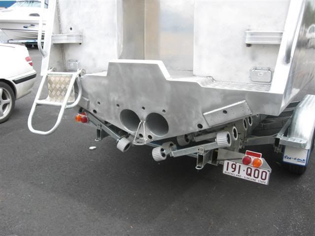
Disregard the ballast tubes.
This will provide extra buoyancy, strength & waterline length plus it will give you a very handy platform to carry out any "on the water" engine work.
I would suggest that the centre section of the transom be cut out & replaced with a new section designed to handle the extra loading. There will probably be less labour involved in replacing the bad metal, although there will be more materials needed. As for an Armstrong bracket, could you get a sealed full-width, full-depth extension fabricated as part of the transom replacement by the one shop. Possibly something like this.
Disregard the ballast tubes.
This will provide extra buoyancy, strength & waterline length plus it will give you a very handy platform to carry out any "on the water" engine work.
Regards,
Pete in Brisbane
Pete in Brisbane
-
gandrfab

- Posts: 600
- Joined: Fri Mar 28, 2008 12:33 pm
- 16
- Your location: Edgewater Fl
- Location: Edgewater Fl
Re: Striker Project Part 1 (request tech input)
Who is the local Alloy fabrication guy ?
bdelaporte wrote:Gentlemen, Thanks for the comments.... keep them coming as I am new to the AL scene. I have had a number of vessels but all NON ALLOY before. I will find out about the location of where the ballast was located and try to determine the type and weight of it. Gandrfab, I will look you up as I live in Winter Park and just left Command of the National Guard Infantry unit in Sanford right on the lake. I was promoted and now work out of St Augustine as an Active Duty Officer in the Army. I will start posting photos as soon as we start working on her. The plan is job completion on 01 September 2009. This will give me the entire Summer to get her together properly. Good call on the weighing, that has been my plan all along. Expectations of performance change throughout the years and I want to ensure that she is up to current standards of power and safety. This should be fun.
Bruce
Re: Striker Project Part 1 (request tech input)
Could you just have a bracket made to mount the new motors on and have the plate where it attaches to the boat just cover all those holes and be welded to the clean metal?
'05 Pacific 1925
Mercury 150
Mercury 150
-
kmorin
- Donator 08, 09, 10, 11, 12, 13, 14, 15, 16, 17, 18, 19, 20, 21, 22, 23, 24
- Posts: 1746
- Joined: Mon Aug 18, 2008 1:37 am
- 15
- Your location: Kenai, AK
- Location: Kenai, Alaska
Transom repair methods
bdelaporte
The pictures show an extremely heavy transom with external poultice corrosion that happens when water is trapped between pieces of aluminum doesn't dry out and as it becomes starved/depleted/deaerated of oxygen; becomes acidic. This case doesn't appear too bad and there seem to be two different types of holes in the stern.
The upper access holes probably don't need solid plate fill, just a good scrub with a sander, wire wheel and some 0.187" plates fore and aft flush to the openings. This would cover the openings that won't have too much to do with a bracket or cantilevered engine mount's stiffness or support. Welding in 3/4" plate is time consuming, multi-pass and will likely be more cosmetically difficult than cover plates.
All the bolt holes in the three mounts or equipment races can be cleaned by over drilling and plug welded on the ends to seal- but access to weld on the forward side is an unknown?
I'm not familiar with the exact details of the bracket you're adding, but your only concern with the level of structural stiffness shown by a 3/4" transom (!) is to make sure the bracket ties into the internal structure since the transom is not a large part of cantilever structural loading. Very likely there are a set of hull longs that line up with the original drives' locations- inside the hull. These will be the main transfer of loads and thrust to the hull inspecting their joint to the transom is critical.
I'm assuming (my favorite form of 'logic') that you'll weld the new aluminum bracket to the hull? In this case the lower transom holes that might be 'inside' the bracket's stern outline (body plan view) and therefore are less critical than would be the case if they were below the future waterline and exposed.
Cost to do work in different areas varies too much for me to intelligently provide cost estimates and not understanding what is in the fabricator's scope of work beyond a bare sketch, I can't say if this is high or not?
There is no reason that is shown in the photos to need to bevel 3/4" plate to fill the openings as none of them are structurally important enough, but since the new bracket isn't clear to me- size, shape, mounting to hull OR the internal structure, then I'm kind of shooting from the hip, in the dark.
just my few cents.
kmorin

Re: Striker Project Part 1 (request tech input)
Grind down to good metal, prep for paint, put a primer down made for metal (no copper), top coat with paint and use better cathodic protection this time. I would think you could just put the bracket on and then weld a plate on the other side and cover the holes up.

-
Chaps
- Donator '09
- Posts: 2246
- Joined: Sun Jan 13, 2008 12:19 am
- 16
- Your location: Seattle, WA
- Location: Seattle, WA
Re: Striker Project Part 1 (request tech input)
Are you saying the transom is 3/4" thick? Thats unusually heavy build. You don't need to spend anywhere near that kind of money. Like others have said, grind away the corrosion, grind out the holes or overdrill them, fill with lighter plate. If you do the prep work I can't see more than $500. Nothing structural there, your just keeping the weather out. I'd suggest bolting a twin engine Porta bracket up to that transom to hang your outboards (unless you're sure you need the buoyancy of a tank bracket). Makes it so easy to tune engine running height for various loads and conditions.
1987 24' LaConner pilothouse workboat, 225 Suzuki

please view and like: https://www.facebook.com/bottompainting/
please view and like: https://www.facebook.com/bottompainting/
-
bdelaporte
- Posts: 14
- Joined: Sat May 30, 2009 7:39 pm
- 14
- Your location: Orlando, FL
Re: Striker Project Part 1 (request tech input)
All, Thanks for the information. Yes, the transom is 3/4" in the mounting area. I agree with kmorin, the topside cowling holes are not structural in nature and can be closed off cleanly with lighter plate. I like the ideas for the smaller holes also. The comments reference the lower corrosion make sense as they may be fully enclosed inside the new bracket. I will post a picture of the type of bracket I plan to have built. I believe that the bracket is the way to go as a full extension would be pretty extensive and pricey. My intent is to mount the bracket traditionally (multiple thru bolts) into the original crossbraces inside the transom, then weld a bead around the entire outside of the flotation chamber. As described by a couple of you, I could just "clean up" the corrosion area, prime and paint as it will be inside of the bracket once mounted. I will most likely do more, but is nice to know the transom is plenty stout enough to work with. I am really looking forward to mounting the engines and taking her out for her (my) maiden voyage. The welder was a guy in St Augustine (Blue water Fabricators). The boat is in dry storage up there right now. Thanks for the comments, keep them coming as this project progresses! :shock:
- Attachments
-
- Armstrong Bracket (Standard)
- Brckt3.jpg (27.12 KiB) Viewed 10212 times
-
- Dropped Swim Platform as needed for my boat
- bracket2.JPG (24.12 KiB) Viewed 10218 times
-
- bracket1.JPG (26.37 KiB) Viewed 10216 times
Re: Striker Project Part 1 (request tech input)
Make sure to keep the bracket paint free...
- Attachments
-
- 101_0558 (Small).jpg (46 KiB) Viewed 10191 times
-
- 101_0549 (Small).jpg (63.27 KiB) Viewed 10189 times
-
- 101_0559 (Small).jpg (49.21 KiB) Viewed 10193 times
-
- 101_0550 (Small).jpg (39.95 KiB) Viewed 10192 times
-
bdelaporte
- Posts: 14
- Joined: Sat May 30, 2009 7:39 pm
- 14
- Your location: Orlando, FL
Re: Striker Project Part 1 (request tech input)
What happened to the paint on the bracket? Most come from the manufacturer power-coated. Did this one get some type of puncture or corrosion damage? What brand bracket is this? Thx
-
Chaps
- Donator '09
- Posts: 2246
- Joined: Sun Jan 13, 2008 12:19 am
- 16
- Your location: Seattle, WA
- Location: Seattle, WA
Re: Striker Project Part 1 (request tech input)
Would suggest you just bolt it on and insert spacers (like hard plastic flat washers for instance) on the bolts between the transom and the bracket so as to create a small gap that can drain properly (assuming it is built as an air tight unit). I don't see the point in welding it on, you may have a need to remove it in the future. If you have areas on the inside of your transom that are difficult to gain access to for thru bolting then simply drill and tap the transom, its so thick you wouldn't necessarily need nuts on the inside.bdelaporte wrote:My intent is to mount the bracket traditionally (multiple thru bolts) into the original crossbraces inside the transom, then weld a bead around the entire outside of the flotation chamber. As described by a couple of you, I could just "clean up" the corrosion area, prime and paint as it will be inside of the bracket once mounted.
1987 24' LaConner pilothouse workboat, 225 Suzuki
please view and like: https://www.facebook.com/bottompainting/
please view and like: https://www.facebook.com/bottompainting/
Re: Striker Project Part 1 (request tech input)
I have to totally agree with Chaps, thru-bolt it on and leave it be. The power coat was cheaply sprayed on and did not adhere to the metal causing it to flake off. Make sure the bracket is air tight, even with a hatch on the top, or get a drain put put in. They never pulled the drain plug on this bracket.
- Attachments
-
- 101_0556 (Small).jpg (88.43 KiB) Viewed 10150 times
-
kmorin
- Donator 08, 09, 10, 11, 12, 13, 14, 15, 16, 17, 18, 19, 20, 21, 22, 23, 24
- Posts: 1746
- Joined: Mon Aug 18, 2008 1:37 am
- 15
- Your location: Kenai, AK
- Location: Kenai, Alaska
Bracket Mount
21ftcc,
That bracket looks like it was cast (!) which is completely outside my experience so I can't remark from one on one knowledge, but- the leak shown looks like it was from internal corrosion not external. The water inside the bracket probably became acidic and ate through the bracket from the inside out. The overall look of the surface appears to be from electrical stray current corrosion, if the bracket weren't bonded to the DC Negative of the engines this could result. Also the zincs are fairly well gone so the boat might also have been in a 'hot' harbor location and that contributed to the external surface paint blistering. To my eye the pin hole and the paint are not common cause. Cast alloys are not the same as welded alloys so protecting most of them with coating systems would be important, with welding alloys, 50_ _ and 60_ _ series, painting is optional except for bottom paint, which still makes sense.
I guess my net point is; that this bracket's circumstances and a welded bracket seem like they'd be quite different in immersion performance.
bdelaporte ,
My concept about welded aluminum boats is their main integrity comes from- welding. I'd weld the bracket on, and if I didn't like what was added after a while, cut it off and weld something else in its place. By cleaning the transom where the bracket mounts, and insuring both meet in a decent physical joint the weld is fast and final. If there are concerns that weld is not tight, then air test the weld by pressurizing the interstitial volume using a fitting mounted inside the bracket or inside the transom.
The reason I don't favor bolting is shown in the original photos.
I'm not confident that plastic spacers would be most seaworthy answer since the bolts, bolt holes on both sides (fore and aft) would have to have some method of sealing (5200 compound?) that was installed on the bolts' shanks/shaft/length that provided the seal. This seams like a potential leak area because any compression deformation of the plastic leaves a bolt loose. Now that fastener is no longer doing its tension job AND the remaining seal is only that material around the fastener inside the aluminum holes drilled oversized to allow some 'goop' into that joint space.
I'd rather trust a MIG bead; just like the rest of the hull.
Structurally the main tie-in to the hull that you want to attain is to the hull longitudinals not the transverse members, although with a 3/4" transom plate to work with, just butt welding to the transom will hold a pair of 300 hp engines without much effort.
As for which design or style of bracket will help the hull the most (?) some of those shown have no planing area, and the lowered stern model with the flooding tubes is of the other type. I'm grouping the two types #1; a bottom extension added planing area and #2; the others that are cantilevered mounts but don't have a lower surface common to the hull's after bottom.
I'd look at the waterline on the hull from the side and try to see how the hull sat at rest? If she was down by the stern very much at all then considering the hull extension type may be worth the extra dollars and effort since that displaced volume will help float the engines. They're moving aft so their stern down moment arm is increasing, so countering that to some extent may be worth considering? If the waterline is fairly parallel to the chine in the after 1/4 of the boat then the added buoyancy aft isn't as potentially helpful since the boat already floated a pair of 'outboards' hung aft without much pitch by the bow.
Performance-wise, moving the engines aft is worth a few knots alone, but trim can contribute to top end as well, so if the boat was heavy by the stern to begin with (tankage, hardware, batteries, console....?) then it's back to considering the bracket as a potential to help make a base trim adjustment by adding planing area aft the longitudinal center of gravity. If the boat had pitch problems before, it hard to image a Striker with pitch problems, but if it did, then the planing bottom engine mount can be wedged a bit to help bring the bow down without engine trim OR tabs.
I'd want to go around the cycle a few times with pros and con's of each type before deciding on one type of engine bracket. Lots of reasons to go one way or the other are already mentioned here but the trim aspect or at-rest-waterline aspect are both worth reviewing.
cheers,
kmorin
Re: Striker Project Part 1 (request tech input)
The comments and explanations are outstanding and the advice forthcoming! Isn't this place great! My vote is for an extension or a full flotation type bracket...reason it would seem to me the two new engines are going to be heavy hanging back there compared to the old SeaDrives, plus any increase in waterline length will by theory increase speed, plus the additional buoyancy will at rest keep her closer to being level.

2009 Raider 185 Pro Fisherman, 2005 90Yamaha, 2012 Yamaha9.9HT, 2008 EzLoader roller, 2004 Dodge TCD dually, 2005/2015 Lance1161
Re: Striker Project Part 1 (request tech input)
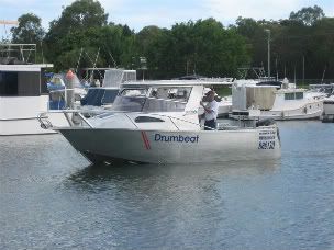
More images of the Extension bracket on the Raider.


Interanly there are two plates running fore and aft to help transfer the thrust welded to the bottom stringers with weep holes and at the boat transom and the bracket transom. Note the taper (fore and aft) of the extension. I have seen other boats of my Make out in the Sound that are traditional transom mounted OB...one had a 90 like mine and the resting attitude was a little bow high compared to mine...so the extra is nice to have!
I vote for a full extension welded on and that would cover much of the old holes (I think)also. Capt PJ
2009 Raider 185 Pro Fisherman, 2005 90Yamaha, 2012 Yamaha9.9HT, 2008 EzLoader roller, 2004 Dodge TCD dually, 2005/2015 Lance1161
-
JETTYWOLF

- Contributor/donator/Location Nazi
- Posts: 6074
- Joined: Sun Jan 06, 2008 9:11 pm
- 16
- Your location: JACKSONVILLE FL USA
- Location: Tree-hugger, USA...they call it FLA.
Re: Striker Project Part 1 (request tech input)
About your "armstrong" bracket idea.......the brackets come with armstrong water proof inspection plates.
you can see them on their web site. And no they don't hold out ever drip of water. They're good, but they aren't super man inspection plates that's for sure.
If it was me, I 'd do like Chaps, or have a bracket built onto the boat. And leave them buy'em brackets alone.
Gawd do they suck on plastic boats. Reminds me of a bandaid or an ez fix rather than redesign. I see a boat with a bracket like that I keep walking.

-
bdelaporte
- Posts: 14
- Joined: Sat May 30, 2009 7:39 pm
- 14
- Your location: Orlando, FL
Re: Striker Project Part 1 (request tech input)
PJ9, nice extension on your vessel. I really like the idea. I will see if anyone here in Florida has the ability to do the same type of work. I know Alloy boats seem to be more popular in your neck of the woods, so I do not know if anyone around here can do the same. What did yours cost? I would think it was quite a bit more than an "bolt-on" bracket? I am curious on how it was tied into your original stringers or just welded onto the outside of the hull. Thanks for your input!
-
gandrfab
- Posts: 600
- Joined: Fri Mar 28, 2008 12:33 pm
- 16
- Your location: Edgewater Fl
- Location: Edgewater Fl
Re: Striker Project Part 1 (request tech input)
bdelaporte..."I will see if anyone here in Florida has the ability to do the same type of work."
Here I am, How can I help you?
Here I am, How can I help you?
-
bdelaporte
- Posts: 14
- Joined: Sat May 30, 2009 7:39 pm
- 14
- Your location: Orlando, FL
Re: Striker Project Part 1 (request tech input)
Gandrfab,
I appreciate the offer for help on the project, when I went to your site I saw t-top, poling platform, tower, leaning post, outriggers,. I did not see any pics or discussion of Alloy boat manufacturing, custom engine brackets and such. I am not an expert by any means, but I do believe that there is a big difference between piping based products and what I am looking to have done.
If you have done this type of work before I would be interested in seeing what you have done and possibly working with you otherwise I desire to stick with someone that has lots of experience at this type of modification since my family's safety will rely upon the work.
-
gandrfab
- Posts: 600
- Joined: Fri Mar 28, 2008 12:33 pm
- 16
- Your location: Edgewater Fl
- Location: Edgewater Fl
Re: Striker Project Part 1 (request tech input)
Sorry Towers are my nich
If I have met 100 people that are great welders, only a small percentage have been able to
make a good weld on anodized aluminum (it's a lot like welding oxidized aluminum) http://www.wisegeek.com/what-is-anodized-aluminum.htm
Many metals are structurally weakened by the oxidation process, but not aluminum. Aluminum can actually be made stronger and more durable through a process called 'anodizing'. Anodizing involves placing a sheet of aluminum into a chemical acid bath, quite often acetone in laboratory experiments. The sheet of aluminum becomes the positive anode of a chemical battery and the acid bath becomes the negative. An electric current passes through the acid, causing the surface of the aluminum to oxidize (essentially rust). The oxidized aluminum forms a strong coating as it replaces the original aluminum on the surface. The result is an extremely hard substance called anodized aluminum.
So my claim to fame is not my boat building experience, but my ability to weld and work with aluminum.
I started as a tig welder working an small parts steal, stainless (not stain free), aluminum, bronze,and copper.
Then a few years building air boats and gas tanks. (miles of mig aluminum)
then some time building communication vans for the news companies (roof racks and compartments all aluminum)
also a few years building road stripping equipment (but that was mostly steel)
Now I am 9 years into burning threw this anodized aluminum self employed, self motivated
So I am not yet a boat builder, but I have yet to come across an aluminum job that has stumped me.
viewtopic.php?f=3&t=399&p=3226#p3226
If you want an engineer, that's fine but most engineers don't get their hands dirty.
I will leave you alone, and best of luck on the boat
Re: Striker Project Part 1 (request tech input)
The bracket is part of the hull plate. Hard to take pics of inside but, I'll explain...the bottom plate is part of the hull plate with the top sides added...the standard transom is constructed as if it were to be a OB but goes all the way up with no cut out to hang the OB in....that would be your original transom...then the sides and inside supports are welded in and the top laid on. The inside supports have extension of the stringers welded into place fore and aft then along side those plates are welded standing up to the inside of the inside forward transom and to the new bracket transom...this provide stiffing for the force of the engine pushing and hanging...the top diamond plate is welded all around and has bent tube along the top edges for additional strength and a good rub rail with a OB transom being made of 2" square/rectangular stock on the outside above the platform and just plate on the inside of the cavity. There is a bilge pump in the cavity and a 2" hole thru the original inside transom to allow drainage...I think I would have left the original transom solid and had an extra cavity with the bracket and had two bilge pumps, but then this allows the drain plug to drain all of the boat, no need to have two plugs. The plastic fittings are drains for the aft bait tank and the forward fish hold and the thrid is the intake for the washdown. note the hull plate flairs inward and has wings on each side and the bracket plates are inboard and lined up with a top to bottom sopprt on thr indie of the insde transom, addtionally there is a channel running across the inside transom to distribute the loads, plus i noticed that when the aft bait tank was installed it becomes part of the structure, so there is many distribution points for the loads...I guess that is why this boat can carry a 150 if you wanted. I think that would be a bit much as she cruises at 19 to 21 and tops at 24 to 26 with a 90 Yamaha. I do hope you can find some good folks to do your work...if you decide to go with my style of bracket, let me know and I'll try to get more defined pics to show your builder. Good hunting! Capt PJ 

2009 Raider 185 Pro Fisherman, 2005 90Yamaha, 2012 Yamaha9.9HT, 2008 EzLoader roller, 2004 Dodge TCD dually, 2005/2015 Lance1161
-
aluminumdreamer
- Donator '10
- Posts: 369
- Joined: Sat Apr 25, 2009 8:45 pm
- 15
- Your location: Mid Coast Maine
Re: Striker Project Part 1 (request tech input)
I guess he must have lost interest? I found this on ebay this morning, too bad looks like it could have been a hell of a boat for the right person.
http://cgi.ebay.com/ebaymotors/32-FT-ST ... ngQ5fBoats
Here is the link to the ebay listing if anyone is interested. There is also another thread about this craft under the title Thomas Marine Industries in Alloy Boat Forum.
Nate.
http://cgi.ebay.com/ebaymotors/32-FT-ST ... ngQ5fBoats
Here is the link to the ebay listing if anyone is interested. There is also another thread about this craft under the title Thomas Marine Industries in Alloy Boat Forum.
Nate.
-
Chaps
- Donator '09
- Posts: 2246
- Joined: Sun Jan 13, 2008 12:19 am
- 16
- Your location: Seattle, WA
- Location: Seattle, WA
Re: Striker Project Part 1 (request tech input)
Nice boat, I wonder what it will go for (or what his reserve is).
1987 24' LaConner pilothouse workboat, 225 Suzuki
please view and like: https://www.facebook.com/bottompainting/
please view and like: https://www.facebook.com/bottompainting/
-
Bob5292
- Posts: 224
- Joined: Wed Jan 09, 2008 11:14 pm
- 16
- Your location: Seattle
- Location: Seattle
- Contact:
Re: Striker Project Part 1 (request tech input)
pjay9: Is that drain plug on the back of your boat brass?
-
bdelaporte
- Posts: 14
- Joined: Sat May 30, 2009 7:39 pm
- 14
- Your location: Orlando, FL
Re: Striker Project Part 1 (request tech input)
Gents, I saw that my ad on this site was pulled, not sure what happened, but yes the vessel is for sale. The e-bay listing was from the broker up in St Augustine. I did not lose interest, but being active duty military and between deployments I just do not have the time to complete. I bought another vessel a few months ago that was fishing ready and have been using it. If anyone is interested in it please let me know. I am open to cash offers above $24k